
Infinite Ground Planes
When defining Perfect E Boundary, Impedance
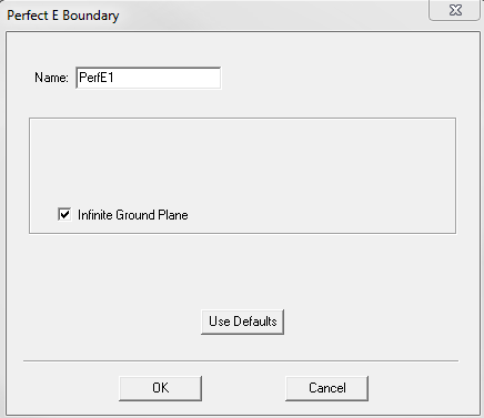
Boundary, or Finite Conductivity Boundary, select the Infinite
Ground Plane check box to model its effects in the simulation. The
following figure shows the Perfect E Boundary dialog box with
this option selected.
For designs with port excitations but no FE-BI boundary and metallic IE region defined, selecting Infinite Ground Plane affects only the calculation of near field and far field radiation during post processing; otherwise, the design has to be re-simulated to model the effects of infinite ground plane.
The boundary condition infinite ground plane divides the problem region into two halves. The entire model resides in the half above the boundary, and the radiated fields are set to zero in the half below the boundary. Antenna parameters involving radiated power are consistent with these properties.
Lossy ground planes can be approximated by selecting the Infinite Ground Plane check box when defining Finite Conductivity Boundary or Impedance Boundary. The effects of these boundary conditions are incorporated in the field solution and in the radiated fields accordingly.
Remember the following requirements when defining an infinite ground plane:
- It must be defined on a planar surface.
- All infinite ground planes and symmetry planes must be mutually orthogonal.
- For impedance, layered impedance, or finite conductivity boundaries, only one infinite ground plane can exist in a design. For perfect E boundary conditions, multiple infinite ground planes are supported and they must be co-planar.
When PML or a standard radiation boundary is used, the FEM model must contain the ground plane on the bottom surface and the PML or radiation boundary on the other surfaces. To achieve accurate results, this restriction must be followed. This restriction does not apply in the following cases:
- When a FE-BI is used for the radiation boundary and the infinite ground plane is modeled as metallic IE region.
- Finite arrays are analyzed using a Finite Array DDM model.