
Define Mode Alignment and Polarity
This section discusses the options under Modes alignment and Polarity that appears on the Wave Port dialog box. First bring up the Wave Port dialog box as follows:
- Select the face that you want to excite, right-click, and select Assign Excitations>Wave Port.
- Name the port.
The three options under Mode Alignment and Polarity are described below.
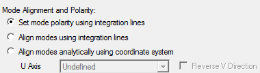
Use Set mode polarity using integration lines
This is the default. Use this option as follows:
- Bring up the Wave Port dialog box, access the Modes panel.
- Enter the number of modes, select the
radio button Set mode polarity using integration lines to control the polarity.
Note:
HFSS will arbitrarily align the E fields of the modes.
 Note:
Note:For more information, see Modes with Default Settings and Set Mode Polarity Using Integration Lines.
Use Align modes analytically using coordinate system
- Bring up the Wave
Port dialog box and select this option.
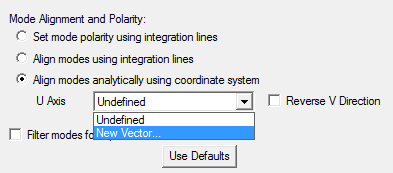
- Select New Vector from the U Axis drop-down menu.
- Draw the U axis to split the port symmetrically.
The V direction is computed automatically and can be flipped using the Reverse V Direction check box. The solver polarizes the fields by aligning them with analytic mode patterns that are generated on the U-V coordinate system.
Note:For legacy projects, when reading in a port, if alignment is requested but only one mode exists, HFSS turns alignment OFF. This prevents an error in validation, and preserves the behavior of having the fields polarized but not aligned.
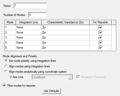
If desired, you can check the Filter Modes for Reporter check box on the lower left (see below).
This adds a new column to the Mode table, which lets you use a check box to designate a mode For Reporter. For designs with multiple modes, this function will simplify your selections when you create traces for reports.
For more information, see Align Modes Analytically Using Coordinate System.
Use Align modes using integration lines
This option meant for advanced users causes polarization for non-analytic ports. There is no restriction on the port geometry, materials, or integration lines.
- Bring up the Wave Port dialog box.
- Specify more than one mode.
- Select Align
modes using integration lines.
A column Alignment Groups is added in the Modes table.
- Select Alignment Groups from the corresponding drop-down menu.
- Define the Integration Lines on the port surface as needed.
For more information about this option and the effect of Integration Lines, see Align Modes Using Integration Lines.