Assigning a Dielectric or Conducting Material to Volumetric Region
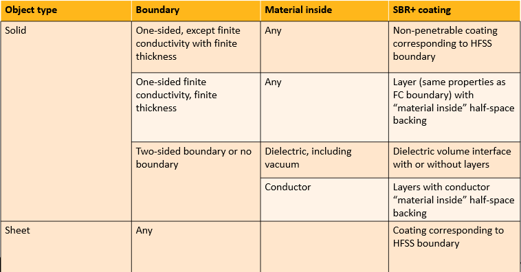
Both materials and boundaries can be assigned to solid objects in HFSS SBR+. Materials can be dielectric with possibly a frequency-independent dielectric and/or magnetic loss tangent, or conductive, with any conductivity σ > 0 S/m. Every boundary type already supported in SBR+ is supported for solid objects, too. For one-sided boundaries, including PEC, PMC and Perfect Absorber, the boundary overrides the material assignment. Two-sided boundaries and materials are used together and translated to a proper SBR+ coating.
When the material assigned to a solid object is dielectric, and either no boundary is present or the boundary is two-sided, rays propagate inside the dielectric region according to Snell’s law of reflection and refraction. SBR+ solid objects can be assigned homogeneous isotropic dielectric materials, making it possible to accurately solve problems involving dielectric regions of non-constant thickness. Dielectric material assignments can include a dielectric and/or magnetic loss tangent. This feature is available for SBR+ solution-type designs and hybrid designs with SBR+ regions.
Dielectric material assignments must be homogeneous, isotropic, and with zero conductivity. Lossy dielectrics can be configured by specifying a frequency-independent dielectric and/or magnetic loss tangent. Dielectric objects can be located in a free-space background, or contained fully or partially within another dielectric region or can be in contact with metal. In SBR+, ray bundles can represent complex wavefronts, and each ray represents a sample of that wavefront that is assumed to be locally planar. Provided that the wavefront is not too irregular, the curvature of the interface varies smoothly and slowly relative to the wavelength scale, such interaction of rays with the boundary of a dielectric region provide a good approximation of the reflection and refraction of an arbitrary wavefront into and out of that region.
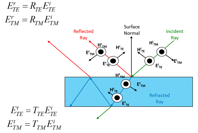
Unlike SBR+ Fresnel coefficient boundaries, which can be thought of as a lumped representation of a finite- and uniform-thickness coating (e.g., Layered Impedance Boundary), material assignments are useful for describing irregularly shaped dielectric regions. Rays hitting a Layered Impedance Boundary do not need to be traced through multiple bounces within the layers because this effect is summarized by the Fresnel coefficients of such a boundary. In contrast, rays hitting a dielectric region interface generate a reflection back into the incidence region and, critically, a refraction ray inside the dielectric region on the opposite side of the interface. The refraction ray will be traced through multiple bounces within the dielectric region, and these subsidiary rays can refract back out of the dielectric region or reflect off or refract into dielectric regions that are embedded within. The reflection and refraction coefficients and ray directions at dielectric region interfaces satisfy Snell’s laws, and they depend on the polarization of the incident wave (ray).
According to the equivalence theorem, only the currents on the free-space side of an interface are radiated to field observers (e.g., far-field angles, other antennas, etc.), with computed fields being valid in free space.
Since rays traveling through dielectric regions follow Snell’s laws, interesting phenomena can occur when transitioning between regions of different refraction indexes. Total internal reflection occurs when a ray impinges beyond a critical angle at the interface between a material with higher refraction index and one with lower refraction index. Consider the case in the following picture.
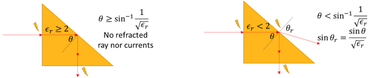
The triangular region is an isosceles right triangle with permittivity ϵr and set within a free-space background. A ray hits one of the legs, enters the dielectric region, and hits the hypotenuse at a 45o θ angle with the surface normal. The ray is then reflected and exits the prism from the other leg. According to Snell’s law, if  , energy does not propagate beyond the dielectric interface, but is completely reflected in the dielectric region. A non-propagating evanescent wave is generated in the region of space immediately outside the hypotenuse side.
Since the SBR+ algorithm tracks the history of encounters with dielectric region interfaces in order to establish whether it has entered or left a dielectric region, it is important to make sure that SBR+ excitations are placed in free-space, and not inside the dielectric volume.
Raytracks starting inside a dielectric region, or that encounter incompatible dielectric region coatings, as in the case of Tolerant or Dynamic meshing with intersecting/contained objects, will be flagged as "inconsistent", and result accuracy can't be guaranteed.
When any boundaries are assigned on top of objects, the material assigned to the object will be used to determine the proper coating information passed to the SBR+ solver. Two-sided boundaries can be placed over dielectric or conductive solid material assignments to represent, e.g., a thin layer of paint over a structure.
In addition, SBR+ supports assigning boundaries on sheets inside dielectric regions.
Material/Boundary to SBR+ Coating