
Applications for Deembedding
Deembedding helps to calculate the S-parameters near or on the plane of a discontinuity or when a long transmission line is attached to the port plane instead of explicitly modeling it in HFSS. For lossless ports, when you deembed them into or out of the model, there is change only in the phase of the S-parameters but not in the magnitude. For lossy ports, aside of the change in the phase of the S-parameters, there is only a slight change in the magnitude. Deembedding saves time and significantly reduces the simulation efforts.
Extract Input Impedance: Use Deembedding
This section describes how to extract the input impedance
in the microstrip fed patch antenna model shown in the following figure.
The port (highlighted in red ink) is placed at an appropriate distance
away from the discontinuity. We cannot place the port near the discontinuity (the intersection
of the trace and the patch antenna). However,
if you want to measure the input impedance at the discontinuity, you
can deembed the port as shown by the blue arrow in the figure.
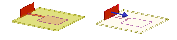
For lossless ports, deembedding will not change the magnitude of the S-parameters. It will only change the phase.
>Modeling Long Transmission Line: Use Deembedding and Port Solver
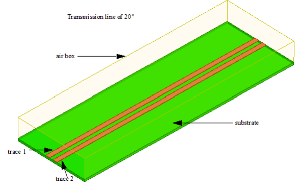
Suppose you want to model a 20 inch differential pair PCB microstrip transmission line as shown below.
Of course you can explicitly draw a 20 inch length of the microstrip model, define a port on either end and extract a 4-terminal S-parameter matrix from the simulation.
However, this model is 2D in the transverse plane since the distribution of the field occurs only in the transverse plane and does not vary in magnitude along the transmission line where all that changes is the relative phase of the fields. To extract S-parameters from such a long transmission line, you only need to model a minimal length of the transmission line and then, deembed the ports - thus leverage the information extracted from the 2D port solver and by deembedding generate all the relevant 2D aspect of the transmission line structure in its entirety.
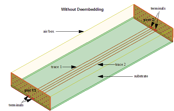
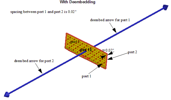
Although this is a 2D problem, HFSS being a 3D simulation tool requires creation of two ports each with two terminals separated by a minimal physical distance. For this separation distance as a rule of thumb use some dimension associated with the cross-section of the transmission line such as the thickness of the trace or the substrate. Such a rule of thumb will ensure a physically small model needing fewer mesh elements than the explicitly long model as well as a mesh with high quality characteristics. Solve the model of this minimal length and then deembed outwards from the ports, using a negative sign in the deembed distance fields to effectively add the additional length to generate a model. This deembedding operation will add the effect of phase delay and additional dielectric and conduction losses to the resulting S-parameter from this model.
We only use the propagation constant (referred to as gamma) to de-embed and characteristic impedance is only needed if renorm takes place.
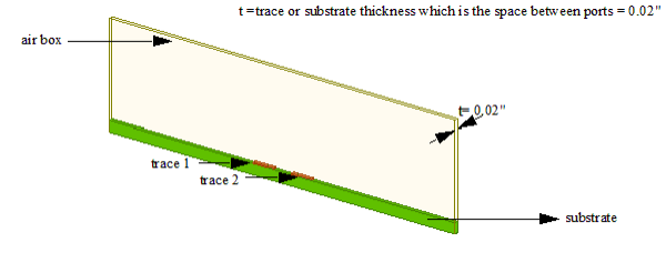
So, in the transmission line model shown in the figures below the explicit model length is 0.02" corresponding to the thickness of the microstrip trace. To extract a 20" length model from such an analysis the ports can be dembedded outwards with a length DL = (20 - 0.02)"/2 = 9.99". This model is 1000 times smaller and the simulation effort is reduced greatly.
The figures below shows the model of a 0.02" transmission line that can be used with deembedding to model a 20" long transmission line.
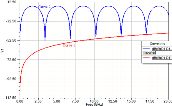
The plot for S-parameters before and after deembedding from the explicitly short model is shown below. The curve 1 (not deembedded) is a typical S(1,1) plot for a short transmission line. Curve 2 (with deembedding) represents the behavior of a long transmission line with many resonances in the frequency range.
Extract Screening Impedance: Use Deembedding
This section shows how to extract the equivalent surface impedance of a screen by deembedding the distance of the ports. A unit cell of a periodic screen is modeled as shown in the following figure. The port is placed at a certain distance away from the scatterer. The screening impedance replaces a scattering planar periodic structure by homogeneous anisotropic boundary conditions.
For more information, see the section on Wave Port Placement
A blue arrow depicts the dembedding distance while the port is selected, once you set the options under Deembed Settings. For a unit cell modeling equivalent screening impedance, the deembedding distances should point to the nearest surfaces of the substrate even if there is a thickness between these surfaces.
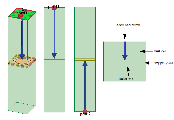
For port 1, the tip of the deembed arrow should touch the upper surface of the substrate. For port 2, it should touch the lower surface of the substrate.
You do not need to re-run a simulation in order to de-embed the S-matrix. Post-processing reports are automatically updated to reflect the deembedded S-matrix.