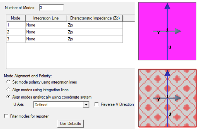
Align Modes Analytically Using Coordinate System
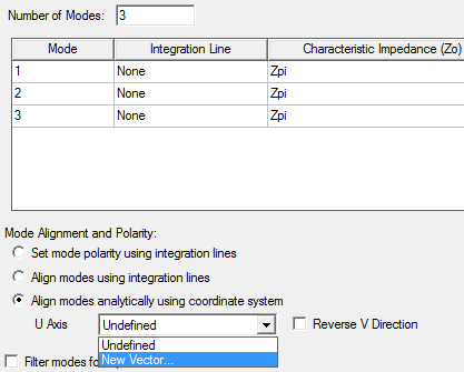
This option is used to align modes for standard waveguides such as square waveguides, rectangular waveguides, coaxial waveguides etc. (For a complete list, see the section Analytic Port Types). On the General tab of the Wave Port dialog box, select the last radio button and New Vector from the drop-down menu. Draw the U-V axes to determine the mode alignment. The U axis must lie on the center of the port plane and split the port into equal haves. Otherwise an error message will pop up.
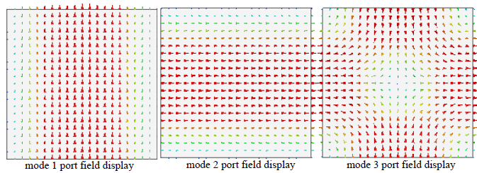
The figures below show the cross-section of a square wave guide for which the U-V axes are set and no integration lines defined for 3 modes. The U-axis must lie along the port plane and split the port into two equal halves. After you define the Solution Setup and run the simulation, the Port Field Display for the 3 modes are also shown in the figures below.