Working with the Components Window
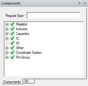
The Components window is a dockable window that is used to view and configure various component settings for Layout components. Use the Components window to select a component or a component class, add ports to a component, and configure multiple ports across components. You can also select multiple components in the Layout editor to configure pins and ports for each simultaneously. The window can be resized and relocated.

To show or hide the Components window on the desktop, click View > Components. A check box appears next to the command if the Components window is visible.
With a component selected, the following configuration controls are available from the right-click menu:
- Type – reclassifies the component type to Resistor, Inductor, Capacitor, IC, IO, or Other.
- Enable/Disable - enables or disables the component.
- Model – opens the Component Model window, where you can change the component model definition, including die, solder ball, and port properties. Changing the model scope will update every reference designator that belongs to the model definition.
- Create Ports on Component – adds ports for the component
- Remove Ports on Component – removes ports for the component.
- Fit Selected – fits the selected component in the active view window.
For more information, see Layout-based Component Encapsulation.
