
Working with the Layers Window
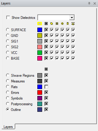
In the Layers window, you can select the working layer and the visibility of layout objects on specific layers, objects such as shapes, pads, components, nets, and the layers themselves. The Layers window is divided into three sections: stackup layers, non-stackup layers, and a pre-process mesh section. This dockable window can be resized and relocated.
- To show or hide the Layers window on the desktop, click View > Layers. A check box appears next to this command if the Layers window is visible.
- To select a working layer, click the radio button of the layer you want to work on.
- To view specific items on different layers, use Show Dielectrics, Zone Filter, the layers check boxes, and View Name drop-down menu.
If the stackup is a multizone stackup, select a zone from the Zone Filter to see the available layers.
The Show Dielectrics check box controls whether dielectric stackup layers are shown. If unchecked, dielectric layers are hidden and holes (vias and pins) are rendered continuously visible from the top-most visible signal layer to the bottom most visible layer. If checked, dielectric layers appear and hole visibility can be finely controlled by each layer (but not necessarily continuously visible).
The View Name drop-down menu lists user-defined views and their controls. You can configure how layers and nets are displayed and then save this visibility as a view. Later, select that view from the drop-down menu to reset the Layout window to it. The view controls and default options are:
- <Surface> shows the top and bottom conducting layers of the layer stackup and hides all other layers. This is the default view.
- Save Current View opens a dialog that allows you to save the current setting of layers and nets to a new layout view.
- Delete View opens a dialog that allows you to delete saved layout views.
Check boxes control what is displayed in a layer. Icons at the top of a column control the entire column. Individual check boxes control the item visibility for the layer corresponding to the check box’s row. Hover over an icon to see what the column controls:
|
Name |
Icon |
Controls the visibility of |
Appears |
| Fill/Unfill All |

|
Color in the object |
Always |
| Show/Hide All |

|
All objects |
Always |
| Shapes |

|
Shapes |
Always |
| Lines |

|
Lines and paths |
Always |
| Pads |

|
Pads |
Always |
| Holes |

|
Holes |
Always |
| Components |

|
Components |
Always |
| Mesh |

|
Mesh of signal layers |
When a pre-process mesh is displayed |
| Background Dielectric Mesh |

|
Mesh of dielectric layers |
When a pre-process mesh is displayed with a laminate stackup |
A pre-process mesh section may appear below the non-stackup layer section. It controls design-wide visibility of:
-
Airbox non-mesh and mesh
-
Hole, solderball, and bondwire mesh
The visibility of these objects is not restricted to their layers. Also, layer visibility check boxes cannot control these mesh visibilities. Non-mesh visibilities are controlled by the layer check boxes.