
Unit Cell of a Phased Array
Description - A unit cell of an infinite phased array of vivaldi antennas is simulated using linked boundaries and a Floquet port.
Model - the antenna is fed by a coax line
with a wave port. The upper face of the unit cell is terminated in a
Floquet port. The sides are two pairs of Primary and Secondary (Lattice pair) boundaries.
The substrate er
= 6 and is 1.27 mm thick. The conducting traces are 2D objects with PerE
boundaries. 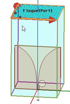
Setup - Adapt at 4.5 GHz with an interpolating sweep from 2 to 5 GHz.
To view a port or boundary, select the desired item in the Project Tree. It is then highlighted in the Model window and the properties will be displayed in the Properties window.
Post Processing
After solving, you can view solution data by right-clicking on Setup1 and selecting Profile to display the Solution dialog. You also view the Solution tabs for Convergence, Matrix Data, and Mesh Statistics.
To view a plot of active S parameter seen at the feed, look in the Project tree and double-click on XY Plot1. To view the modes present on the Floquet port click on the desired mode under Port Field Display>Floquet Port 1 in the Project tree, and a vector plot of the mode will be displayed.
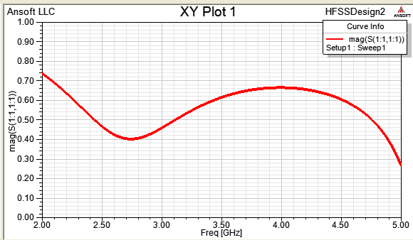
This design was analyzed in “Analysis of Periodic Structures via a Time-Domain Finite-Element Formulation with a Floquet ABC,” L.E.R. Peterson et al., IEEE Trans, AP, March 2006, pp 933-944. You will see the plot computed here agrees nicely with Fig. 9b in the reference.