
Stripline (Driven Terminal)
The following figure shows the HFSS model of the GSSGSSG Stripline.
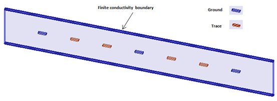
GSSGSSG Stripline
The figure illustrates a set of seven striplines composing a GSSGSSG dual differential pair configuration. To reduce the coupling between the differential pairs there are 3 ground conductors. Notice how the terminals are defined in the model shown below.
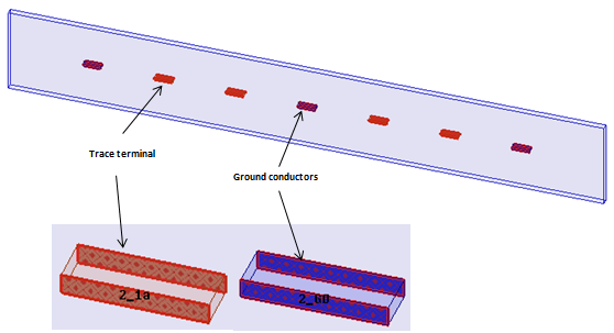
Terminals
The grounding is accomplished when you renormalize the impedance of the ground conductors to a very small value like 5e-6 (6 orders of magnitude below the other terminals set to 50 ohms). Notice the contrast in the values of the terminal renormalizing impedance of a trace and a ground conductor in the dialogs below.
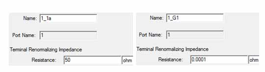
Terminals Dialogs
To model a longer length, just deembed the ports as shown below.
Ports with Deembedding
In the Post Processing tab of the Wave Port dialog box the deembedding distance = + (Simulation Length - Model Length)/2 where Simulation Length and Model Length are the design variables.
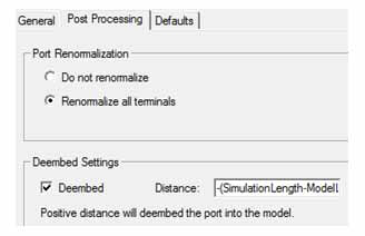
Post Processing Deembed Setting
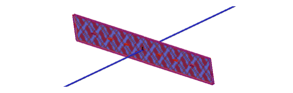
The mesh plot is shown below.
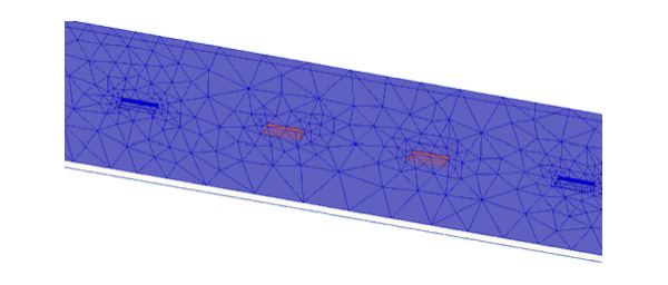
Stripline Mesh Plot
The results for the S-parameter plot are shown below.
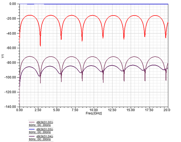
Stripline S-Parameter Plot