Getting Started with Ansys Electronics Desktop
The Ansys Electronics Desktop, shown in the following figure, provides a comprehensive environment for designing and simulating various electronic components and devices. The Electronics Desktop consists of a unified user interface where electromagnetic designs, thermal designs, and circuits can be created. Typically, you can create or import a design, set up the simulation, validate your design, run the analysis, and post process the results.

The desktop includes the following design types:
-
-
-
-
-
-
-
-
-
-
-
- Simplorer – an integrated, multi-domain, mixed-signal simulator for complex technical systems. Simplorer is a subset of the Twin Builder standalone product. Please see the Twin Builder help for more information.
-
-
You can access all of these design types and features from the Project menu, and any combination of design types can be inserted into a single project file. The schematics can be used to wire up the different field solver models and create a model of a high-level system. Ansys Electronics Desktop provides an efficient way to manage complicated projects that require several different analysis tools to model all of their pieces. Designs can also be parameterized. With the help of the Optimetrics feature, the best design variations can be made available to other modules when the designs are linked into a higher-level simulation. This lets you study the effect of varying a design parameter on the behavior of the entire system.
You can access these design types and features from the Windows launcher. You can use the ACT Toolkit for HFSS-EMA3D Datalink to launch and use this tool.
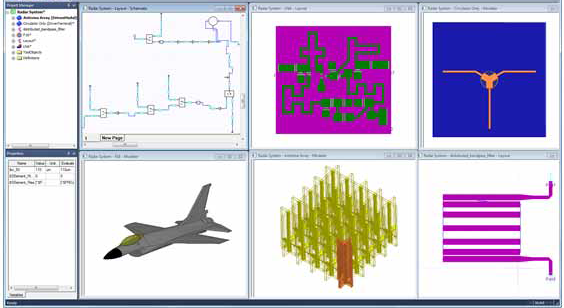
The following illustration shows how the Ansys Electronics Desktop can be used to model different components for radar system analysis. An antenna array created in HFSS is linked to an IE design of an F16 aircraft. The low noise amplifier and bandpass filter are two important components in the receiver part of the radar module circuit design. The low noise amplifier and the filter can be modeled in HFSS 3D Layout and linked together in a circuit simulation, along with other components of the radar module connected to the antenna array. The outputs of the radar module can be used to drive the antennas using the push excitation feature, whereby the voltages on the antenna array ports can be automatically set to correspond to those of the driving circuit. The push excitation feature enables the user to view electromagnetic fields when the array is driven by the radar module circuit.