Ferrite Circulator
Description -In this example, a three-port ferrite circulator as shown in fig.1 is analyzed at 8 GHz. This non-reciprocal network transfers power from incident port to the adjacent port in a clockwise or anti-clockwise direction and isolates the third port. The nonreciprocity of the ferrite circulator is achieved by proper magnetic bias fields.
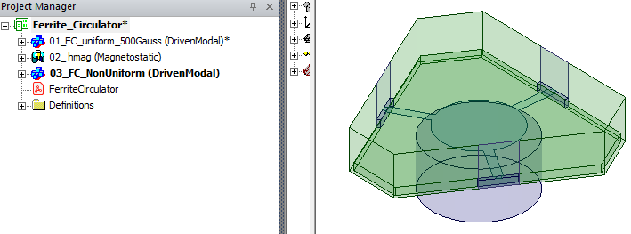
Model - This example demonstrates how to model a ferrite circulator in HFSS with uniform and non-uniform magnetic biasing. The project Ferrite_Circulator.aedtz contains three designs: “01_FC_uniform_500Gauss” to solve for uniform magnetic bias, 02_hmag(Magnetostatic) to solve magnet with non-linear material in Maxwell to establish non-uniform biasing and “03_FC_NonUniform” to solve the ferrite circulator in HFSS by linking the fields from Maxwell as a non-uniform magnetic bias on the ferrite.
Most circulator use permanent magnets for the bias field which possibly introduce nonuniform magnetic bias. The design 2_ hmag consists of a magnet of finite size and a ferrite disk. The Maxwell 3D tool based on Maxwell magnetostatics solver is used to solve non-linearity of ferrite material. Note that there are no boundaries and excitation settings required in Maxwell to get magnetic DC bias. However, users can assign currents and different assignments according to the requirement.
The FerriteCirculator pdf in the project gives details for running the simulations and interpreting the results.
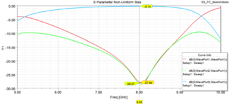
The S parameters plots shown in the following plot show results for a non-uniform biased magnetic field.
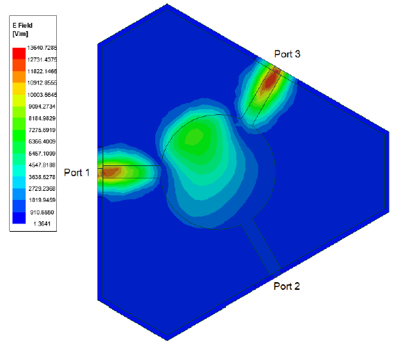
The electric field plot shows that all the power is being transmitted to port 3 and nothing is going to port 2.