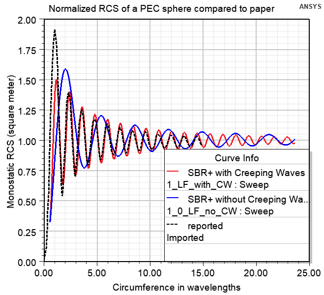
Monostatic RCS of a PEC Sphere Using SBR Solver with Creeping Waves
Description - The simulated geometry is a perfectly conducting sphere of radius 0.56419 meter. Monostatic RCS value of such a sphere in the optical region is 1 square meter. The term creeping wave refers to fields that propagate along smoothly curved surfaces. Finite fields in the shadow of a curved surface are due to the propagation of a creeping wave. Creeping waves decay quickly as they propagate, since they progressively shed energy to space along their direction of travel. As the curved structure increases in electrical size, the shadow region fields become weaker. Hence, while creeping waves keep propagating on a continuous smooth surface, such as a sphere, the currents they paint on a surface are important only up to a certain traveled distance. The goal of this example is to show how to simulate the Monostatic RCS of a sphere vs. frequency using SBR+ solver and compare the results simulated with and without enabling CW option.
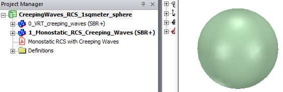
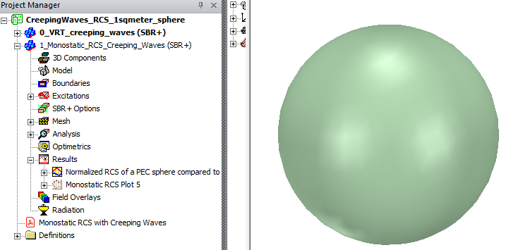
This example demonstrates how to use Creeping Waves (CW) option for RCS simulations of a conducing sphere in HFSS SBR+ design type. The project “CreepingWaves_RCS_1sqmeter_sphere” contains two designs: “0_VRT_creeping_waves” to visualize the CW rays and choose the proper CW setup options; “1_Monostatic_RCS_Creeping_Waves” to simulate the Monostatic RCS values. The Monostatic RCS with Creeping Waves pdf includes details and guidance on using and interpreting the model.
Design “0_VRT_creeping_waves”
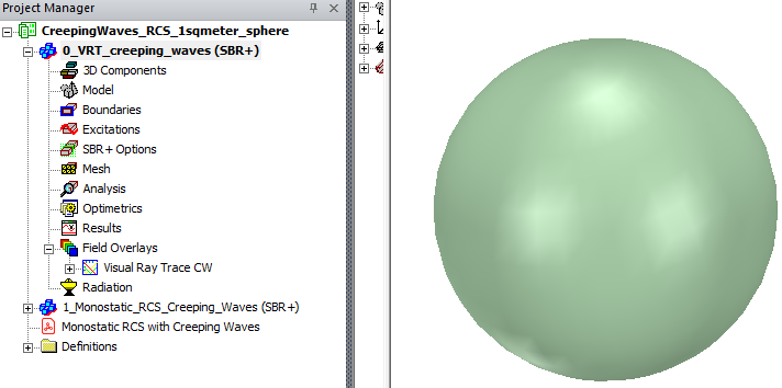
Design “0_VRT_creeping_waves”. VRT (Visual Ray Tracing) of creeping waves analysis is recommended to help configure the creeping wave settings. Note that there is neither excitation nor setup present in this design – VRT analysis and setups are completely different from the RCS solution setup. To add VRT plot, right click on Field Overlays in the Project Manager, choose Plot VRT > Creeping Waves.
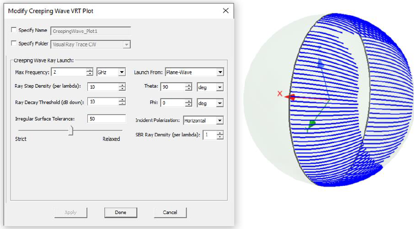
You are encouraged to investigate how different options change the CW rays. Selecting Visual Ray Trace CW and CreepingWave_Plot1 entries in Project Manager window, one can edit and investigate options in the Properties window. See more details about CW rays in Appendix 1 of the Monostatic RCS with Creeping Waves pdf included in the Project.
1_Monostatic_RCS_Creeping_Waves
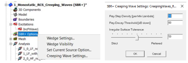
This model has 4 Analysis setups for Monostatic RCS of the sphere to cover two frequency ranges and to compare results with and without CW option enabled. CW options are part of SBR+ options and set throughout the design.
Since enabling the CW options adds simulation time, you should consider the results from VRT CW.
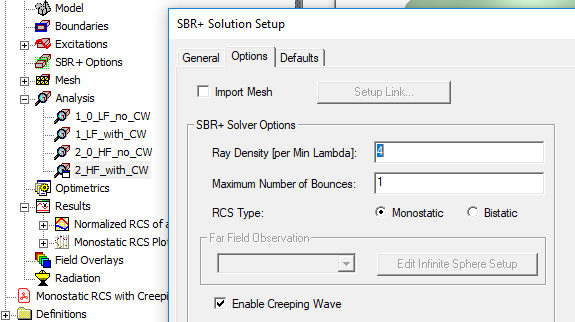
The same design might have several solution setups with and without creeping waves options. CW option is enabled in Options Tab of solution setup (see Fig.2). Setup 1_0_LF_no_CW: frequency from 0.05GHz to 2GHz, CW is not enabled Setup 1_LF_with_CW: frequency from 0.05GHz to 2GHz, CW is enabled Setup 2_0_HF_no_CW: frequency from 1GHz to 10GHz, CW is not enabled Setup 2_HF_with_CW: frequency from 1GHz to 10GHz, CW is enabled.
The project includes reports.