Limit Lines in 2D and Circuit Cartesian Plots
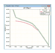
Limit lines are simple graphical representations of constraints on XY plots. These are modeled as a sequence of XY point pairs. For example, designate a single limit line to delineate either an upper or lower limit, or two limit lines to delineate upper and lower limits. Add as many limit lines as you want. You can control the display properties of the line including color and hatch width.

To create a limit line:
- Click Report2D>Add Limit Line, or right-click an XY plot and select Add Limit Line.
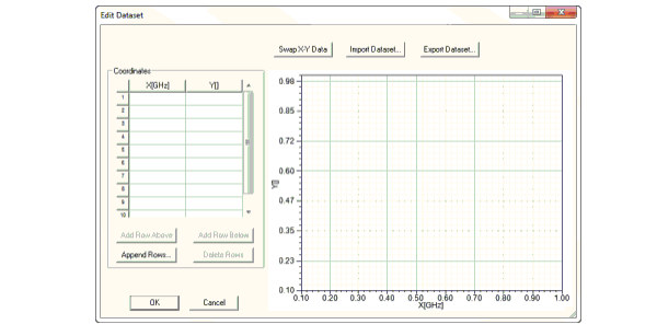
This opens an Edit Dataset window.

- You can use this window to:
- Enter the XY coordinate values directly.
- Import XY values from a tab-delimited .tab file.
- Export dataset to a file.
To add additional data points, click Append Rows ..., or modify the table by clicking Add Row Above, Add Row Below, and Delete Rows, as necessary.
You can press Shift +click to select multiple adjacent rows, or Ctrl+click to select any combination of rows for deletion.
- Click OK to add the limit line you defined to the plot. The line divides the plot into two regions in the context of its length. By default, the upper region is hatched to designate constraint violation.

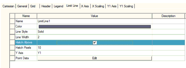
- You can select the limit line in the plot to edit its properties on the Limit Line tab of the plot properties.

- Line properties: color, style and width
- Hatch direction (hatch above or below the limit line)
- Hatch width in pixels
- Y axis association
- The point data that defines the limit line itself
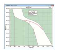
- If you add a second limit line, designate it as hatch below by unchecking Hatch Above to produce a “tunnel” marking the upper and lower constraints.

