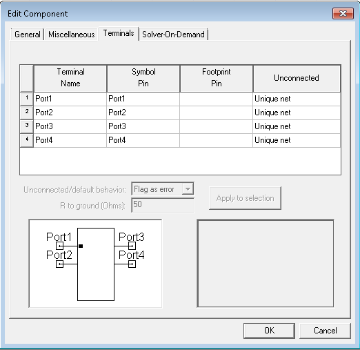
Components Terminals Tab
To line up component terminals in an envisioned order, Click the Terminals tab to associate each symbol pin with the proper terminal by first ordering the symbol pins, then selecting the corresponding symbol. This allows you to visually associate the symbol pins with the netlist properties for the simulation model. The symbol and footprint preview windows at the bottom of the window are automatically updated to reflect whatever changes you make to the symbols and footprints you modify.

The following controls are available:
In the Terminals display window, click one or more terminals directly, which then enables the following window options:
Unconnected/default behavior – Used to specify the response when a pin is not connected to a wire or port in a schematic. Choose between the following drop-down menu actions: No action (default), Flag as error, and Grounded. Click Applytoselection to apply your changes to the selected terminals.
R to Ground – If you select Grounded for the Unconnected/default behavior, then specify the resistance to ground in the R to Ground entry window. Click Applytoselection to apply your changes to the selected terminals.
Click OK to save your changes and close the window, or click Cancel to close the window without saving any changes.
