Generating a Regions Schematic in HFSS 3D Layout
From the SIwave sweep setup, you can generate an HFSS regions schematic. This affords greater control and visibility into the HFSS region setups.
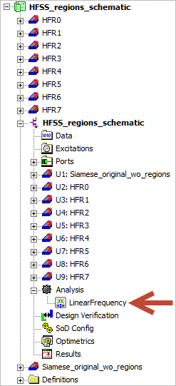
Each HFSS region is modeled as a separate 3D Layout design under a single 3D Layout project. There is an additional design showing what is left after the other regions are removed. Once these 3D Layout projects have been instantiated in AEDT, a schematic design is generated. A Nexxim LNA sweep setup (that matches the S-parameter sweep) is inserted and the schematic is ready for simulation. Prior to solving, you can examine and modify each associated 3D Layout project.
Modifications to ports at region interfaces, if done carelessly, can invalidate the schematic level connections and requires user intervention to rectify.
To generate an HFSS regions schematic:
- Set up an SIwave regions simulation.
- From the Edit Frequency Sweep window, click HFSS (user-defined regions) and Generate regions schematic (do not simulate).
Note:
If the Generate regions schematic option is unavailable, ensure that Solve regions in parallel is deselected. These options are mutually exclusive.
- Click OK.
- Right-click the simulation and select Analyze.
Instead of running a simulation, Electronics Desktop generates the schematic. It looks similar to the following:

Note the location of the LNA sweep setup.
