HFSS 3D Model Extents
The HFSS 3D Layout type can be simulated directly using HFSS. To achieve this, the bounding computational region (extents) for HFSS must be defined. The airbox's extents can have a type that is independent of the dielectric's extents.
Define or Edit HFSS 3D Model Extents
- To open the Set HFSS Model Extents window, do either of the following:
- From the Layout ribbon, click HFSS Extents.

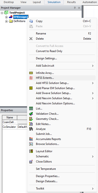
- From the Project Manager window, expand the Project Tree (e.g., TestProject). Then right-click the active design (e.g., EMDesign1) and select HFSS
Extents.

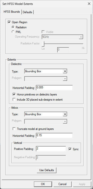
The HFSS Bounds tab displays by default.

- From the Layout ribbon, click HFSS Extents.
- Set the following options:
- Open Region – allows support for Radiation boundaries or perfectly matched layers (i.e., PML) boundaries in HFSS 3D Layout.
- Radiation – selects a radiation open region.
- PML – selects a PML open region, with the following additional options:
Note:
The PML option only works with bounding box extents because their geometry generation with PML has fewer corner and edge regions. When PML is selected:
- Do not select Truncate Model at Ground Layers. It is incompatible with PML.
- Horizontal Padding must be greater than zero.
- Visible – sets visibility of PML boundaries.
- Operating Frequency – select a frequency of PML boundary calculation from the drop-down menu and enter a value, which is automatically converted to GHz.
- Radiation Factor – controls the thickness of PML boundaries, on a scale of 0 (thinnest) to 10 (thickest).
- Extents – these settings control extent types and padding. Dielectric and Airbox can have different extent types:
- Type – specifies the method used to derive the
base-polygon for the extents region. Options include:
- Bounding Box – the base-polygon is calculated as the bounding box of all active layout geometry across all layers.
- Conformal – the base-polygon is calculated as the union of all active layout geometry across all layers.
- Convex Hull – the base-polygon is calculated as the convex hull of all active layout geometry across all layers.
- Specifiy the following parameters, depending on whether they reside in the Dielectric or Airbox areas:
- Dielectric – the base-polygon is defined by the exact dimensions of the zone extents input by users on the Outline layer. Horizontal Padding is deactivated and any existing value in the Horizontal Padding field is ignored.
- Airbox – creates a union of the zone extent polygons on the Outline layer and the user-entered value in the Horizontal Padding field to set airbox extents.
- Polygon – the base-polygon can be selected from any polygons present on user layer types. This option is only available when one or more polygons are on an assembly, outline, or user layer.
- Polygon – presents a list of polygons for selection when Polygon is the selected Type. The polygons must be on an assembly, outline, or user layer.
- Dielectric – these settings define how the polygon for dielectric
and negative signal layers is generated relative to the base-polygon:
- Horizontal Padding – an expansion factor (i.e., unitless fraction) or absolute offset (e.g., 0.005, 0.15) to be applied to the base-polygon in constructing HFSS geometry for dielectric layers.
- Honor primitives on dielectric layers – If checked, and layout geometry is present on a dielectric layer, that geometry is created for the HFSS simulation. If not checked, the geometry is ignored and an expanded base-polygon is created (checked by default).
- Include 3D placed sub-designs in extent – If checked, and sub-design is 3D placed, the parent design extent will include the sub-design region. If not checked, the sub-design region's geometry will not be included in the parent design extent (unchecked by default).
- Airbox – these settings define how the airbox is generated
relative to the base-polygon:
- Truncate Model at Ground Layers – if ground layers are present such that regions above or below are electromagnetically isolated from all sources, selecting this option caps the simulation volume at these elevations. Any horizontal padding on the airbox is ignored. This option is not compatible with PML.
- Horizontal Padding – an expansion factor or absolute offset to be applied to the dielectric-polygon in constructing the HFSS geometry for the airbox. For PML, This must be greater than zero.
- Vertical – these settings specify expansion factors for the Z-dimension:
- Positive Padding – the expansion factor or absolute offset for the +Z dimension of the airbox. When applying as an expansion factor, the base dimension is the maximum of either length or width of the dielectric-polygon.
- Negative Padding – the expansion factor or absolute offset for the -Z dimension of the airbox.
- Sync – synchronizes Positive Padding and Negative Padding settings.
Note: The calculations for Airbox extents changed in version 2020 R2: the vertical padding is calculated by multiplying the vertical padding factor to the stackup height. Previously, the vertical padding was calculated based on the horizontal extents. If a pre-2020 R2 design is opened in the current version, the vertical padding factor adjusts to keep the absolute vertical extent the same. If a design has no stackup height, its vertical padding factor is applied to the horizontal extent.
- Type – specifies the method used to derive the
base-polygon for the extents region. Options include:
- Use Defaults – resets the entire window to default settings.
- Open Region – allows support for Radiation boundaries or perfectly matched layers (i.e., PML) boundaries in HFSS 3D Layout.
- If appropriate, do the following to set the defaults:
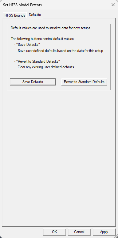
- Click the Defaults tab to display the following:

- Chose a default option:
- Save Defaults – saves user-defined defaults based on the data for this setup (for all tabs).
- Revert to Standard Defaults – clears any existing user-defined defaults (for all tabs).
- Click the Defaults tab to display the following:
- To analyze the existing HFSS simulation setup to obtain information about the PML materials in the results project folder, click OK.
View or Hide the Extents
To view the extents, either click Layout > Draw HFSS Air Box on the menu bar, or on the Layout tab, click the down arrow adjacent to HFSS Extents > Show. A bounding box appears in the Layout Editor. To hide the bounding box, select Layout > Draw HFSS Air Box, or select Hide on the HFSS Extends drop-down menu on the Layout tab.
