
Coupled Resonator Band Pass Filters
Coupled resonator band pass filters are narrow band approximations of band pass filters. The advantages to using coupled resonators over classical band pass filters are: more desirable element values at high frequencies, and flexible element value selections.
Coupled resonator filters are selectable by checking the "Coupled Resonators" checkbox in the band pass schematic tool bar in schematics that support coupled resonator filters, as shown below:

Coupled Resonator Filter Selection Example
Coupled resonator filters consist of a series of LC resonant pairs or mutually coupled coils coupled together with capacitors or inductors. Usually capacitors are chosen due to the lower cost and higher performance. FilterSolutions allows one to select one of the LC resonant element values, and will calculate the other element values needed to create the desired filter.
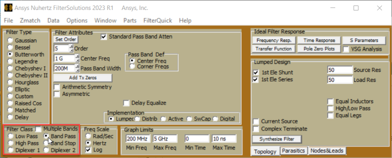
To create a band pass resonant filter:
-
Select the desired filter type from the Filter Type group box.
-
Select Band Pass in the Filter Class group and then create the passive circuits.
-
The passive circuit will have a check box in the menu for Coupled Resonators select this option.
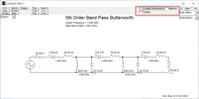
A coupled resonant band pass filter will be displayed. The first element of the filter will match the series/shunt selection in the Passive Control Panel. If the selected pass band is too wide, you will receive an error message informing you that you need to reduce the width of the pass band.
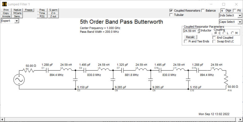
When the resonant filter is displayed, the Coupled Resonator control panel is displayed in the upper right of the circuits window. You are offered the choice of inductor, capacitor, or mutual coil coupled resonators, coupled resonators with or without end coupling elements, and you may select new resonator element values. Capacitor coupled resonators may have their inductors changed. Inductor coupled resonators may have their capacitors changed. Mutual coupled resonators may have their capacitors changed. Enter the desired inductance or capacitance, and select "Recalc" to update the filter. Coupled resonator filters without end coupling elements require third order are higher to redesign with different elements.
Swap End LC for More Symmetric Response
The "Swap End LC" option is available whenever "End Coupled" is checked. Coupled resonator filters have an asymmetrical frequency response characteristic that may be undesirable. If a more symmetric frequency response is desired, selecting the "Swap End LC" option will swap the positions of the outer inductors and capacitors, and apply a narrow band transformation that will restore a narrow band frequency response approximation that is more symmetric, but at the expense of slightly more error in the pass band. The additional error is generally negligible for narrow band filter, but increased for mid band filters. Visual inspection is recommended prior to using the "Swap End LC" option.
Alternatively, the right mouse key may be used to swap outer inductor and capacitors on any band pass filter with an outer inductor and capacitor of differing orientation.
Coupled Resonator Example:
Below is a classical 4th order Butterworth band pass filter with center frequency 500MHz and a band width of 40MHz. Notice some capacitor values are less than 1 pF, and some inductor values are below 1 nH.

Classical Band Bass Filter
Below is the series resonance capacitor coupled band pass filter: Capacitor values are now more reasonably in the low pF range, and all inductor values are 10 nH. However, more capacitors are required to build this filter.

Capacitor Coupled Series Resonator Filter
The magnitude frequency response error is shown below. Dark blue baseline traces depict the true Butterworth response. Yellow depicts the coupled resonator filter response. Note that the error is only significant at frequencies of very high attenuation.
Resonator Coupled Frequency Error
Inductor coupled and mutual coupled resonators skew in the opposite direction. End couplings reverse the skew direction from no end coupling solutions.
Mutual coupled resonators use vertical bars to denote coupled coil, which are in turn coupled with series or shunt capacitors.

Mutual Coupled Resonator Example