
Equal Inductor Band Pass Filters
All Pole Filters
All pole band pass and Zigzag filters nay be constructed using one inductor value only. See the Zigzag section for information regarding Zigzag equal inductor filters. For all pole filters, that is, filters without stop band zeros, the unequal inductor topology may be transformed into an equal inductor topology. Unlike odd order zigzag filter, the all-pole band pass filter requires a fixed single inductor value that is not user selectable. In the case of odd order equally terminated filters, this transformation has no effect on the source resistance. For even order and unequally terminated filters, the source resistance changes. If the source resistance is required to be a fixed value, the "Set Source Res" option will synthesize the filter with two inductor values instead of one.
Synthesizing all pole filters with one inductor value has the obvious advantage of requiring fewer expensive inductor values. It also has the advantage that designs can be produced that place a shunt capacitor at each node. Shunt node capacitors may be used to absorb parasitic node capacitance and eliminate or minimize distortion due to parasitic node capacitance. For medium or wide band filters, this is especially desirable, because tubular filters require narrow bands and cannot be synthesized for medium and wide bands.
Medium and wide band equal inductor band pass filters sometime require negative element values. When this happens, it may be possible to remove them by narrowing the band width or order. If it not feasible to narrow the band width or order, equal inductor will probably not work for the application and the option should be deselected.
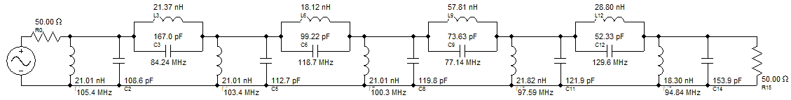
The example below is a 3rd order Chebyshev with 10MHz center frequency and a 10MHz band width.
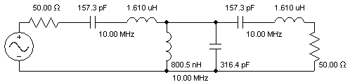
Classic Unequal Inductor Design
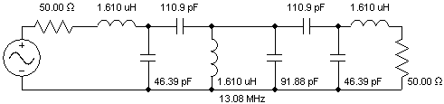
Equal Inductor Design with One Inductor Value
Note that the equal inductor design above contains only one inductor value and contains a shunt capacitor at every node. The expense for these nice features was the addition of two extra capacitors. Also note that physical symmetry is maintained in the equal inductor design.
Stop Band Filters ("Parametric" Filters)
Stop band filters of Chebyshev II, Hourglass, and Elliptic filters may have all shunt inductors or all series inductors set to the same value. Such filters are sometimes referred to as "Parametric". Equal inductor designs for stop band filters sometimes improves the inductor spread ratio for medium and narrow band filters, and in the case of shunt inductors, has the added benefit of providing a shunt capacitor to all nodes so that parasitic node capacitance may be easily absorbed. The price is that a few more inductors are required.
It should be noted that Equal Inductor Zigzag filters have the capability to reduce the inductor spread ratio to unity (perfect), but may result in negative inductor values. In these cases, an equal inductor classical band pass filter may offer improved inductor spread ratios over both the standard zigzag and the standard classical filters.
Equal inductor classical stop band filters alter the source resistance somewhat. If this is objectionable, the "Set Source" Res" selection will restore the source resistor at the expense of fewer equal inductors and possible inductor spread ratio.
Example:
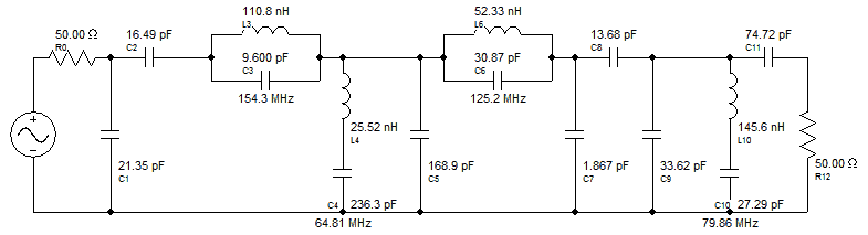
Below is an example of a 20% band width, steep cutoff, 5th order Elliptic filter in classical and Zigzag topologies, followed by the equal inductor counterpart.
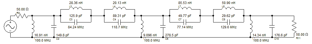
Classical and Zigzag Elliptic filters
Equal Inductor Classical Topology (Some shunt inductors altered slightly to restore 50 Ohm source resistance)
The equal inductor Zigzag filter would have negative elements in this case, and cannot be used for the vast majority of applications. The inductor spread ratios and inductor counts are as follows:
| Topology | Inductor Ratio | Inductor Count |
|---|---|---|
| Classical | 9.40 | 7 |
| Zigzag | 5.71 | 4 |
| Equal Inductor, Zigzag | --- Negative Values | NA --- |
| Equal Inductor, Classical | 3.19 | 9 |
It is easily seen that the Equal Inductor Classical topology produces smallest inductor spread ratio in this case, and is useful in cases where inductor count is not critical.