
Bands

Bands in EMIT define the operating parameters (channel frequencies, power levels, modulation, etc.) for their parent radio. The bands appear as children of the radio. A radio can have any number of bands, and folders can be used to organize the bands. Children of the band node contain the specifications for Tx (Tx Spectral Profile) and Rx (Rx Spectral Profile) characteristics for the parent band. Multiple bands can be assigned to the radio's port.
All bands contain a Tx Spectral Profile and Rx Spectral Profile node as children. When both of these are enabled the band can be both Tx and Rx (i.e., a transceiver). When only one or the other is enabled the Band can only Tx or Rx.
The Band icon changes to indicate the Tx and/or Rx functionality of the Band as shown below where the VHF Band is a transceiver band, the UHF Band is a transmitter band, and the GPS band is a receiver band.

Bands can be plotted to show their Tx and/or Rx spectral characteristics by selecting the Band node in the configuration tree. When plotting a band, you can switch between displaying the Tx or Rx characteristic (for a transceiver band) and the channel frequency by clicking on the trace label at the bottom of the plot.
Port: Defines which radio port is to be associated with the band. Multiple bands can be assigned to the radio's port. Note that at the current time radios are limited to a single port.
Use DD-1494 Mode: When installing radio systems on a military base or other Department of Defense sites, it is necessary to obtain equipment certification from the National Telecommunications and Information Administration (NTIA) by submitting DD form 1494, Application for Equipment Frequency Allocation. The DD form 1494 includes the proposed technical characteristics of the overall system, transmitter, receiver, and antenna (ref. DD 1494 Preparation Guide). Many of the properties that EMIT requires to define Tx and/or Rx characteristics can be found in the DD-1494 for a particular radio, and these DD-1494's are frequently available and provide a useful source of data for creating radio models in EMIT. In these cases, enabling the Use DD-1494 Mode option in EMIT causes EMIT to change some of the labels on its data fields to correspond to the nomenclature used in the DD-1494. This simplifies the process of copying data from the DD-1494 into EMIT.
In cases where there is a difference in the Properties window due to enabling the DD-1494 mode, both versions of the Properties panel will be shown and explained in this manual.
Modulation: Contains the parameters that define the particular signal modulation associated with the band.

With the Emission Designator unselected (False), the channel bandwidth and modulation is defined by the user.
Channel Bandwidth: The bandwidth of the tuned channel.
Modulation: The modulation type is selected via the drop-down Modulation menu. The particular parameters shown depend on the modulation type selected.
For Rx channels, the selected modulation type affects the Rx Spectral Profile in only two ways:
- For digital modulation types, it provides a processing gain parameter to be entered in the Rx Spectral Profile properties panel.
- For AM modulation, the provided modulation index is used to compute the Rx susceptibility as follows:

For Tx channels, the shape of the fundamental emission (as well as the harmonics) is determined by the specifics of the particular modulation being used. EMIT offers a menu of modulations and the parameters associated with the modulation scheme change when different modulations are selected. EMIT approximates the spectral shape for each modulation type using a worst-case step-wise representation. The details on the specific modulation types currently supported in EMIT and their associated properties are provided in the following. Further details regarding Tx emissions can be found in the Tx Spectral Profile section of this documentation.
Generic
Ideal, constant level spectrum across the specified channel bandwidth.


Channel Bandwidth: The bandwidth of the tuned channel.
AM
Amplitude Modulation. In the figure below, Ac represents the carrier power level.


Channel Bandwidth: The bandwidth of the tuned channel.
Max Modulating Freq. (MHz): The highest frequency of the modulating waveform.
Modulation Index: The AM modulation index.
LSB
Lower Side Band. Spectrum is below the suppressed carrier (channel) frequency.


Channel Bandwidth: The bandwidth of the tuned channel.
Max Modulating Freq. (MHz): The highest frequency of the modulating waveform.
USB (Upper Side Band)
Spectrum is above the suppressed carrier (channel) frequency.


Channel Bandwidth: The bandwidth of the tuned channel.
Max Modulating Freq. (MHz): The highest frequency of the modulating waveform.
FM
Frequency Modulation. Bandwidth based on Carson's rule.


Channel Bandwidth: The bandwidth of the tuned channel.
Max Modulating Freq. (MHz): The highest frequency of the modulating waveform.
Freq. Deviation (MHz): FM frequency deviation.
FSK
Frequency Shift Keying. Worst-case envelope computed by EMIT as shown below for 2-FSK (left) and 4-FSK (right). After the specified number of sidelobes the spectrum drops to the noise floor, in this example defined as -25 dBm.


Channel Bandwidth: The bandwidth of the tuned channel.
Bit Rate (kbps): Data rate of the baseband digital signal.
Sidelobes: Number of sidelobes to include in the Tx spectrum before dropping to the noise floor.
Freq. Deviation (MHz): Frequency deviation.
FSK Type: Specific type of FSK modulation desired.
MSK
Minimum Shift Keying. Worst-case envelope computed by EMIT as shown below. After the specified number of sidelobes, the spectrum drops to the noise floor, in this example defined as -25 dBm.


Channel Bandwidth: The bandwidth of the tuned channel.
Bit Rate (kbps): Data rate of the baseband digital signal.
Sidelobes: Number of sidelobes to include in the Tx spectrum before dropping to the noise floor.
PSK
Phase Shift Keying. Worst-case envelope computed by EMIT as shown below. After the specified number of sidelobes, the spectrum drops to the noise floor, in this example defined as -25 dBm.


Channel Bandwidth: The bandwidth of the tuned channel.
Bit Rate (kbps): Data rate of the baseband digital signal.
Sidelobes: Number of sidelobes to include in the Tx spectrum before dropping to the noise floor.
PSK Type: Specific type of PSK modulation desired.
Radar
The spectral masks are calculated using the Radar Spectrum Engineering Criteria (RSEC) defined by the National Telecommunications and Information Administration (NTIA) in the "Manual of Regulations and Procedures for Federal Radio Frequency Management." A copy of the manual can be obtained from the NTIA's website (NTIA Manual of Regulations).

The RSEC specifies various types of radars (CW, FM-CW, FM Pulse, Non-FM Pulse, and Phase Coded) as well as multiple "Groups" (or Criteria). The specific group that a radar belongs to is primarily determined by its function, operating frequencies, and peak or average power levels. Based on the type of radar and the group that it belongs to, the RSEC then specifies the emission mask limits of the transmitted spectrum. EMIT computes the in-channel region of the radar spectrum based off the 40-dB bandwidths specified by the RSEC. The broadband noise level is then defined based off the specified slope from the 40-dB bandwidth points down to the X-dB (ultimate suppression level) bandwidth points.
In some cases the RSEC does not fully define the emission mask limits for a specific radar type and group. For these cases, EMIT defaults to the limits specified for Group C radars, which in general are 'All radars not included in Group A, B, D, or E.
Periodic Clock
The spectrum consists of the fundamental clock frequency and its harmonics. If the Duty Cycle = 0.5, then only the odd harmonics are produced.


Clock Duty Cycle: Defines the clock's duty cycle. A Duty Cycle = 50% (0.5) will suppress the clock's even harmonics.
Clock Rise/Fall (ns): Specifies the rise/fall time of the clock pulses. The rise/fall time impacts the amplitudes of the clock harmonics.
The peak voltage that specifies the clock drive voltage is entered in the Tx Spectral Profile settings.
Spread Spectrum Clock
The Spread Spectrum Clock (SSC) differs from the Periodic Clock in a key way. It is represented in EMIT as a broadband power spectral density (PSD) rather than as a narrowband spectrum. This is due to the spreading nature of the clock. As seen below, the envelope of the spectrum is that of a sinc(x) wave.
Since the SSC signal type is modeled as a broadband PSD, plots of the spectrum are in units of dBm/Hz (despite "dBm" being displayed).
Spread Spectrum Clocking can significantly reduce the peak EMI levels radiated by a system clock. The reduction in the peak levels relative to the peak EMI of a non-spread clock is shown below. EMIT uses a Resolution Bandwidth of 1 Hz for all plots of the SSC spectrum.


Clock Duty Cycle: Defines the clock's duty cycle. A Duty Cycle = 50% (0.5) will suppress the clock's even harmonics.
Clock Rise/Fall Time (ns): Specifies the rise/fall time of the clock pulses. The rise/fall time impacts the amplitudes of the clock harmonics.
Spreading Type: Specifies the method used to tune the clock frequency over. The tuning ranges, where BW = fclockx(Spreading %), are specified as:
Low Spread: fclock-BW < f < fclock
Center Spread: fclock-(BW)/2 < f < fclock +(BW)/2
High Spread: fclock< f < fclock +BW
Spread Percentage (%): Determines the bandwidth over which the clock frequency is tuned.
The peak voltage that specifies the clock drive voltage is entered in the Tx Spectral Profile settings.
PRBS
The Pseudo-Random Bit Sequence (PRBS) spectrum is represented in EMIT as a broadband power spectral density rather than as a narrowband spectrum and it defines the spectrum of a random bit stream. As seen below, the envelope of the spectrum is that of a sinc(x) wave. As with the SSC signal type, since the PRBS signal type is modeled as a broadband PSD, plots of the spectrum are in units of dBm/Hz (despite "dBm" being displayed).
Due to the specialized nature of the PRBS signal type, care must be taken when specifying the Channel Frequencies in the Configuration. For a PRBS, the Frequency Range should be set to 1 Hz in order to result in a valid Tx channel.


Bit Period (ns): Binary stream's bit period in nanoseconds. The bit period is equal to the width of a single bit.
The peak voltage that specifies the clock drive voltage is entered in the Tx Spectral Profile settings.
PRBS (Periodic)
A narrowband representation of a repeating (periodic) Pseudo-Random Bit Stream. As seen below, the envelope of the spectrum is that of a sinc(x) wave.
Due to the specialized nature of the PRBS (Periodic) signal type, care must be taken when specifying the Channel Frequencies in the Configuration. For a PRBS (Periodic) Channel Set, the Frequency Range must be set to (1/Bit Period)/(# of Bits) Hz in order to result in a valid Tx channel.


Bit Period (ns): Binary stream's bit period in nanoseconds.
# of Bits: Length of the binary sequence that is repeated.
The peak voltage that specifies the clock drive voltage is entered in the Tx Spectral Profile settings.
Differential Pairs
Models the common mode narrowband spectrum resulting from the delay skew between a differential pair.


Clock Rise/Fall (ns): Specifies the rise/fall time of the clock pulses. The rise/fall time impacts the amplitude's of the clock harmonics.
Delay Skew (ps): The time delta when one half of a differential signal does not transition at exactly the same time as the other half which can be caused by one of the signal source switching at a slightly different time or different trace or wire lengths between the pair.
The peak voltage that specifies the clock drive voltage is entered in the Tx Spectral Profile settings.
Channel Frequencies
Defines the discrete channel frequencies for the band. The channels begin at the Start Frequency and increase by the Channel Spacing up to the Stop Frequency. Each band in EMIT is limited to 100,000 total channels. If more than 100,000 channels are required, then the band should be duplicated with the frequency range divided between the two bands. Note that both bands can still be assigned to the same radio port in this situation.
A Tx Offset can be specified in which case the Tx channels will be offset by this amount from the Rx channel frequencies as specified by the Start and Stop frequencies.

RF Channeling Capability (in DD-1494 Mode): Defines the discrete channel frequencies for the band. The channels begin at the Start Frequency and increase by the Channel Spacing up to the Stop Frequency. Each band in EMIT is limited to 100,000 total channels. If more than 100,000 channels are required, then the band should be duplicated with the frequency range divided between the two bands. Note that both bands can still be assigned to the same radio port in this situation.
A Tx Offset can be specified in which case the Tx channels will be offset by this amount from the Rx channel frequencies as specified by the Start and Stop frequencies.

Use Emission Designator: An emission designator utilizes a seven-character “word” to represent the bandwidth, modulation, nature of signal, and type of information transmitted by a particular radio. When this is available, EMIT can determine the modulation parameters that it needs automatically from the emission designator. To do so, Use Emission Designator is selected and the designator is entered into the Emission Designator field. For example, for the designator given by 25K0F1D, EMIT's Modulation dialog is displayed as:

The table below lists all the supported modulations and the "EMIT modulation" that they are automatically converted to.
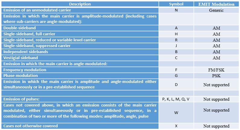
Where the emission designator has been used to determine the associated channel bandwidth and modulation type. In some cases, the user may wish to change the channel bandwidth as determined from the emission designator and this can be done by selecting the Override Emission Designator BW option, in which case the bandwidth entered will override that defined by the emission designator. In the example shown below, a channel bandwidth of 50KHz will be used by EMIT instead of the 25KHz defined by the emission designator (see above).
