
Coupling Models
The following coupling models are available:
- General Parameters
- S-Parameter
- Custom
- Path Loss
- Two Ray Path Loss
- Log Distance
- Hata
- Walfisch-Ikegami
- Erceg
- Indoor Propagation
- 5G Channel Model
General Parameters
These are general parameters that can be added to any of the Path Loss coupling models in EMIT. This includes all Coupling Models except for the S-Parameter and Custom coupling models. By default, these parameters are not applied to the various coupling models.
Propagation Modifiers: Add margins to the path loss coupling model propagation loss to account for uncertainties in the propagation environment. Most of the modifiers are constant for all frequencies (i.e. they add the same amount of margin to the coupling at every frequency). The exceptions are the Rain Attenuation and Atmospheric Absorption modifiers in which the amount of additional attenuation is a function of frequency.

Custom Fading Margin: Adds a specified margin to the path loss coupling to account for uncertainties in the propagation environment.
Polarization Mismatch: Adds a specified margin to the path loss coupling to account for losses due to a mismatch in the polarization of the Tx and Rx antennas.
Pointing Error Loss: Adds a specified margin to the path loss coupling to account for errors in aligning the main beams of the Tx and Rx antennas. Pointing error loss is more significant in highly directional antennas separated by a large distance.
-
Fading Type: Specifies the fading environment for the coupling model. Options include:
-
Fast Fading: Fading due to multipath and modeled as a Rayleigh distribution.
-
Shadowing: Shadowing or "slow fading" is typically due to the motion of one or both terminals and is the result of variations in the terrain over time. This uncertainty is expressed as a random amount of shadowing loss and is modeled as a Gaussian random variable with zero mean and a specified standard deviation.
Fading Availability: The availability (or reliability) of a communications link. The higher the availability, the greater the margin needs to be.
Std Deviation: The standard deviation representing the shadowing loss.
Include Rain Attenuation: If true, EMIT computes the additional attenuation due to rain for all frequencies. EMIT's rain attenuation model is based on the recommendations of ITU-R P838-3.
Rain Availability: The availability (reliability) of the communications link. The procedure specified in ITU-R P838-3 requires that the availability is in the range 99%-99.999%.
Rain Rate: The rain rate (mm/Hr) at the desired location. The rain rate specified should correspond to the location's rain rate that is exceeded 0.01% of the time. Rain rate values for most locations can be found in ITU-R P.837-6.
Polarization Tilt Angle: Polarization tilt angle relative to horizontal. For example, 45 degrees for circular polarization, 0 degrees for horizontal polarization, and 90 degrees for vertical polarization.
Include Atmospheric Absorption: If true, EMIT computes the additional attenuation due to atmospheric absorption for all frequencies. EMIT's atmospheric absorption model is based on the recommendations of ITU-R P676-11.

Temperature: The temperature (degrees Celsius) at the location of interest. If the antennas are at different locations, then an average value can be used.
Total Air Pressure: The total air pressure (hPa) at the location of interest. If the antennas are at different locations, then an average value can be used.
Water Vapor Concentration: The water vapor concentration (g/m3) at the location of interest. If the antennas are at different locations, then an average value can be used.
S-Parameter
The S-Parameter coupling model in EMIT uses an N-port scattering matrix for antenna coupling. The S-matrix is obtained from a Touchstone File supplied by the user. To add an S-matrix to the project, right-click on the Couplings node and select Add S-Matrix File. EMIT shows the following prompt:

Select Yes to automatically create N antennas in the scene and associate them with the N ports of the imported S-matrix. Move the antennas to their intended position using the individual antennas' property panels. If you select No, EMIT does not create any antennas, allowing you to associate the S-matrix with antennas that already exist in the scene or create new antennas manually.
After reading in the Touchstone file, EMIT creates an S-Parameter node using the Touchstone filename (without extension) as the node name. Since EMIT implicitly assumes a 50-Ohm impedance for all RF Systems, all Touchstone files are normalized to a 50-Ohm reference impedance. Multiple Touchstone files can be imported into an EMIT project, each resulting in a separate S-Parameter coupling node.
Imported S Parameter files are considered the highest fidelity coupling model in EMIT and are automatically used by EMIT when they are available for a specified antenna pair. EMIT supports N-port S parameter files, and each file can be toggled on/off within EMIT.
The following options are available from the S-parameter property panel:

EMIT will also use optionally defined port labels. The port labels must be defined in the comment lines of the Touchstone file as shown below. The comment lines must start with a "!" and the ports are then specified by "Port[X] = [port label]" where X is an integer specifying the port number and [port label] is a string label. The labels can also be used as the antenna names (P7-P13 below) or they can just be used for the port label (P1-P6 below).

Enabled: Toggle on/off the use of an individual S parameter coupling file. If disabled, EMIT will not use the S parameter file for any simulations.
Filename: The name of the Touchstone file containing the S-parameter coupling data.
Enable EM Isolation: When enabled, EMIT computes the worst-case coupling, that is, “EM Isolation,” for imported coupling data to account for matching networks. The resulting coupling is computed assuming a conjugate match for each antenna pair at each frequency. This provides a worst-case coupling estimate in cases where the S-parameter data may not include the effects of matching networks. (ref. J. Rahola , Bandwidth potential and electromagnetic isolation: Tools for analyzing the impedance behavior of antenna systems, Proceedings of the EuCAP 2009 conference, Berlin, March 23-27, 2009).
The figure below shows a comparison between simulated S-parameter coupling data before and after EM Isolation is applied. Note that for all frequencies, the coupling computed via EM Isolation is equal to or worse than the initial data which is expected since it assumes a perfect antenna match at each frequency.
- Magnitude (dB) plot.")
Ports: The N ports of the S-matrix need to be 'connected' to the antennas with which they are associated in the EMIT scene. Under the Ports folder in the S-Parameter property panel, a list of ports will appear as shown in the figure above (the figure above is for a 5-port S-matrix). A pull-down menu next to each port number will allow an antenna in the scene to be 'connected' to the corresponding port of the S-matrix. If EMIT created antennas for each port when the Touchstone file was imported then these associations will have been made automatically. Otherwise, the pull-down menus should be used to make the associations.
It is not required that all ports be associated with an antenna. For example, a valid EMIT scenario may only need to use a subset of the N-port S-matrix to define the coupling between antennas.
Notes: The Notes field provides a text area for the user to enter a description of the Scattering Matrix file. The notes are stored with the project.
Custom Coupling
Custom Coupling allows multiple constant coupling values to be defined over unique ranges for an antenna pair. This is done on a piece-wise linear nature, with a "fixed value" for the coupling defined at each frequency of interest. In this way, users can quickly approximate the in-band and out-of-band regions for the antennas and perform a rough cosite analysis prior to obtaining any detailed antenna-to-antenna coupling data.
- Magnitude (dB) plot.")
There is no limit to the number of Custom Coupling nodes that can be specified for a project. This provides a lot of flexibility in terms of how each Custom Coupling node is defined since each Custom Coupling node can then be assigned a different priority. For example, two Custom Coupling nodes and a Path Loss Coupling node can be defined for a project with the Custom Coupling nodes specifying the coupling at "low" and "high" frequencies where the Path Loss Coupling model may be less accurate for the given application. Additionally, antenna tags can be used to group one or more antennas so that a single Custom Coupling node can be used across multiple antenna-to-antenna interactions. The following options are available from the Custom Coupling property panel:

Enabled: Toggle on/off the use of the Custom Coupling node. If disabled, EMIT will not use this Custom Coupling node for any simulations.
Antenna A: Specify the first antenna in the Custom Coupling node's antenna pair. Note that "(all)" can be used to assign all of the project's antennas to the coupling model and that antenna tags can also be used to specify a group of antennas. If Antenna A = 'Group A' and Antenna B = 'Group B', then all combinations of antennas from Group A to Group B or from Group B to Group A will use the coupling model
Antenna B: Specify the second antenna in the Custom Coupling node's antenna pair. Note that "(all)" can be used to assign all of the project's antennas to the coupling model and that antenna tags can also be used to specify a group of antennas. If Antenna A = 'Group A' and Antenna B = 'Group B', then all combinations of antennas from Group A to Group B or from Group B to Group A will use the coupling model.
Custom Coupling Values: The Custom Coupling Values table allows users to specify the coupling in a piece-wise linear nature. Each Custom Coupling node allows the users to specify the coupling at any number of frequency points. EMIT then linearly interpolates between the specified frequency/attenuation pairs to create a wide-band coupling trace over the node's frequency range (i.e. from the minimum frequency specified in the node to the highest frequency specified).
Path Loss Coupling
The Path Loss coupling model computes the coupling between antennas based on the distance between the antennas according to the following equation:

The antenna locations are defined via the property panel for each antenna. The figure below shows the path loss as a function of frequency for two antennas separated by a distance of 10 m.
The Path Loss model is only valid if the antenna's position has been defined and for frequencies for which the antennas are in the far field. These frequencies are defined using the common far field/near field boundary:


The Path Loss model will also include the antenna gains along the line-of-sight (LOS) path between the two antennas. Note that EMIT does not account for any physical objects in a scene and thus will compute the LOS gain between two antennas even if they are physically blocked (e.g. opposite sides of a fuselage) if the Path Loss Coupling model is used. In scenarios such as these, it is recommended to use a full wave (HFSS) or asymptotic solver (SBR+) to obtain the coupling and then to import that data into EMIT as a S-matrix coupling file.
The Path Loss model also contains (optional) Propagation Modifiers. These enable margins (e.g. due to rain attenuation, atmospheric absorption, shadowing, etc) to be added to the "base" value of coupling computed by the coupling model.
The following options are available from the Path Loss Coupling property panel:

Enabled: Toggle on/off the use of the Path Loss Coupling node. If disabled, EMIT will not use this Path Loss Coupling node for any simulations.
Antenna A: Specify the first antenna in the Path Loss Coupling node's antenna pair. Note that "(all)" can be used to assign all of the project's antennas to the coupling model and that antenna tags can also be used to specify a group of antennas. If Antenna A = 'Group A' and Antenna B = 'Group B', then all combinations of antennas from Group A to Group B will use the coupling model.
Antenna B: Specify the second antenna in the Path Loss Coupling node's antenna pair. Note that "(all)" can be used to assign all of the project's antennas to the coupling model and that antenna tags can also be used to specify a group of antennas. If Antenna A = 'Group A' and Antenna B = 'Group B', then all combinations of antennas from Group A to Group B will use the coupling model.
Two Ray Path Loss Coupling
The Two Ray Path Loss coupling model assumes that there are two dominant signal paths between the Tx and Rx antennas. These are the line-of-sight (LOS) path and a reflected path as shown in the figure below.
 path and a reflected path diagram.")
The two signals combine, constructively and destructively, at the receive antenna resulting in peaks and nulls in the received power. The coupling between the antennas is a function of the frequency and the distance between the antennas and can be computed according to the following equation:

The Two Ray Path Loss coupling model is typically used to model propagation environments with minimal multipath fading and a large separation between the antennas. These conditions result in the two dominant propagation paths shown above.
The following options are available from the Two Ray Path Loss Coupling property panel:

Enabled: Toggle on/off the use of the Two Ray Path Loss Coupling node. If disabled, EMIT does not use this Two Ray Path Loss Coupling node for any simulations.
Antenna A: Specify the first antenna in the Two Ray Path Loss Coupling node's antenna pair. Note that "(all)" can be used to assign all of the project's antennas to the coupling model and that antenna tags can also be used to specify a group of antennas. If Antenna A = 'Group A' and Antenna B = 'Group B', then all combinations of antennas from Group A to Group B will use the coupling model.
Antenna B: Specify the second antenna in the Two Ray Path Loss Coupling node's antenna pair. Note that "(all)" can be used to assign all of the project's antennas to the coupling model and that antenna tags can also be used to specify a group of antennas. If Antenna A = 'Group A' and Antenna B = 'Group B', then all combinations of antennas from Group A to Group B will use the coupling model.
Path Loss Coefficient: The Path Loss coefficient is a function of the material properties of the reflecting surface. For small angles, the reflection coefficient is -1 as there is a 180 degree phase change on reflection.
Points/Peak: The two ray Path Loss coupling model has many peaks and nulls due to the constructive and destructive interference resulting from the reflected signal. The Points/Peak parameter specifies the number of frequency points used to model the peaks in the coupling. Increasing the number of points will improve the accuracy, but may also increase the simulation time.
Hata Coupling
The Hata Coupling model (with the COST 231 extension) is an empirical model developed to estimate the propagation loss in various complex environments. As an empirical model, it is derived from measurements at different frequencies across multiple sites. The Hata Coupling model is particularly popular for estimating median path loss in macrocellular systems.
The Hata Coupling model provides an estimate of the median path loss as a function of carrier frequency, base station and mobile station antenna heights, and the distance between the base station and mobile station. The Hata Coupling model is applicable over the following range of parameters:

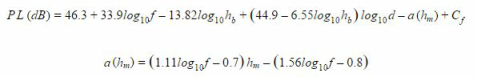
The Hata coupling model defines the median path loss in an urban environment by:

For a large city with dense building clutter and narrow streets, the mobile station antenna correction factor is:

For a small or medium size city, where the building clutter density is smaller, the mobile station antenna correction factor is:

For a suburban area, the same mobile station antenna correction factor used for small/medium cities is applicable, but the median path loss is modified to be:

For a rural area, the same mobile station antenna correction factor used for small/medium cities is also applicable, but the median path loss is modified to be:

The European Cooperation in the field of Scientific and Research (COST) group extended the original model developed by Hata to also cover propagation environments in the 1500-2000 MHz band. This was necessary due to the popularity of cellular PCS deployments and subsequent cellular enhancements. The other model parameters listed above are still applicable to the COST extension. The median path loss for the COST-231 Hata model is:
For metropolitan centers the correction factor Cf=3 dB and for small/medium sized cities and suburban centers with medium tree density the correction factor Cf=0 dB. This model is also recommended by the WiMAX Forum for system simulations and network planning of macrocellular systems in both urban and suburban areas for mobility applications.
The following options are available from the Hata Coupling property panel:
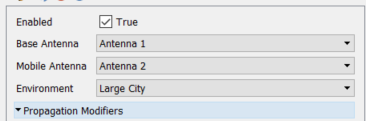
Enabled: Toggle on/off the use of the Hata Coupling node. If disabled, EMIT will not use this Hata Coupling node for any simulations.
Base Antenna: Specify the base station antenna(s) in the Hata Coupling node's antenna pair. Note that "(all)" can be used to assign all of the project's antennas to the coupling model and that antenna tags can also be used to specify a group of antennas. If Base Antenna = 'Group A' and Mobile Antenna = 'Group B', then all combinations of antennas from Group A to Group B will use the coupling model.
Mobile Antenna: Specify the mobile antenna(s) in the Hata Coupling node's antenna pair. Note that "(all)" can be used to assign all of the project's antennas to the coupling model and that antenna tags can also be used to specify a group of antennas. If Base Antenna = 'Group A' and Mobile Antenna = 'Group B', then all combinations of antennas from Group A to Group B will use the coupling model.
Environment: Specifies the propagation environment where the antennas are located.
Walfisch-Ikegami Coupling:
The Walfisch-Ikegami Coupling model is an empirical model developed to estimate the propagation loss in various complex environments. As an empirical model, it is derived from measurements at different frequencies across multiple sites. While the Hata Coupling model is suitable for macrocellular environments, it is not recommended for smaller cells with radii less than 1 km. The Walfisch-Ikegami Coupling model, on the other hand, is recommended for modeling these microcellular environments. The model assumes an urban environment with several characteristics of the environment specified as inputs. Diffraction is assumed to be the main mode of propagation and the model is valid over the following range of parameters:

The Walfisch-Ikegami model distinguishes between the non-line-of-sight (NLOS) and the LOS cases. For the NLOS case, the loss is composed of the terms free space loss, Lfs, multiple screen diffraction loss, Lmsd, and roof top to street diffraction and scatter loss Lrts:
 and LOS equations.")
The roof top to street diffraction and scatter loss term describes the coupling of the wave propagating along the multiple screen path into the street where the mobile station is located. In COST 231, the following street orientation was developed and the Walfisch-Ikegami equations for Lrts are specified:

The heights of buildings and their spatial separations along the direct radio path are modelled by absorbing screens for the determination of Lmsd:

Where the term ka represents the increase of the path loss for base station antennas below the roof tops of the adjacent buildings. The terms kd and kf control the dependence of the multi-screen diffraction loss versus distance and radio frequency, respectively.
For the LOS case (i.e., urban canyon), the path loss has a strong LOS component between the base station and mobile station and the median path loss can be computed as:

The following options are available from the Walfisch-Ikegami Coupling property panel:

Enabled: Toggle on/off the use of the Walfisch-Ikegami Coupling node. If disabled, EMIT will not use this Walfisch-Ikegami Coupling node for any simulations.
Base Antenna: Specify the base station antenna(s) in the Walfisch-Ikegami Coupling node's antenna pair. Note that "(all)" can be used to assign all of the project's antennas to the coupling model and that antenna tags can also be used to specify a group of antennas. If Base Antenna = 'Group A' and Mobile Antenna = 'Group B', then all combinations of antennas from Group A to Group B will use the coupling model.
Mobile Antenna: Specify the mobile antenna(s) in the Walfisch-Ikegami Coupling node's antenna pair. Note that "(all)" can be used to assign all of the project's antennas to the coupling model and that antenna tags can also be used to specify a group of antennas. If Base Antenna = 'Group A' and Mobile Antenna = 'Group B', then all combinations of antennas from Group A to Group B will use the coupling model.
Path Loss Type: Specifies the path loss type for the Walfisch-Ikegami node. The path loss type can be either line-of-sight (i.e., urban canyon) or non-line-of-sight (NLOS).
Environment: Specifies the propagation environment where the antennas are located.
Roof Height: Specifies the typical roof height for the location of the antennas.
Distance Between Buildings: Specifies the typical building to building separation for the location of the antennas.
Street Width: Specifies the typical width of the streets for the location of the antennas.
Incidence Angle: Specifies the angle of incidence of the signal from the base station to the mobile station.
Indoor Propagation Coupling
The Indoor Propagation Coupling model can estimate indoor propagation loss. One use for this ability is in site planning to ensure adequate coverage while minimizing the number of access points required. In Recommendation P.1238-7, the ITU recommends a site-general model which requires minimal path or site specific information. The model assumes that both the base station and the portable terminal are located inside the same building and the indoor radio path loss is then characterized by both an average path loss and its associated fading statistics.
The recommended model accounts for the loss through multiple floors which enables planners to reuse frequencies between floors. The power loss coefficients specified for the model include an allowance for transmission of the signal through walls, obstacles, and other loss mechanisms that are common in buildings. This differs from site-specific models which would require explicitly accounting for the loss due to each wall the signal passes through. The basic indoor path loss model has the form:

The tables (from ITU-R P.1238-7) below have some typical parameters for various frequency ranges and building types, which were derived from measurements at various locations. Note that EMIT's implementation of the site general model only includes data for which there is both a power loss coefficient and a floor penetration loss factor. Additionally, if there is data for one building type at a particular frequency, but the other building types are missing that data, then EMIT defaults to the values for the building type that is available.


The following options are available from the Indoor Propagation Coupling property panel:

Enabled: Toggle on/off the use of the Indoor Propagation Coupling node. If disabled, EMIT will not use this Indoor Propagation Coupling node for any simulations.
Antenna A: Specify the first antenna in the Indoor Propagation Coupling node's antenna pair. Note that "(all)" can be used to assign all of the project's antennas to the coupling model and that antenna tags can also be used to specify a group of antennas. If Antenna A = 'Group A' and Antenna B = 'Group B', then all combinations of antennas from Group A to Group B will use the coupling model.
Antenna B: Specify the second antenna in the Indoor Propagation Coupling node's antenna pair. Note that "(all)" can be used to assign all of the project's antennas to the coupling model and that antenna tags can also be used to specify a group of antennas. If Antenna A = 'Group A' and Antenna B = 'Group B', then all combinations of antennas from Group A to Group B will use the coupling model.
Building Type: Specifies the type of building (e.g. office building, commercial building, residential apartment, or residential house) where the antennas are located.
Number of Floors: Specifies the number of floors between the antennas specified for the Indoor Propagation coupling model. The data specified in ITU-R P.1238-7 limits this to 3 floors or less.
Custom Building Values: Enables a custom indoor environment to be specified in terms of the power loss coefficient and floor penetration loss factors as a function of frequency. Unlike the data in ITU-R P.1238-7, there is no limit on the number of floors that these values can represent.
Log Distance Coupling
The Log Distance Coupling model is a generic extension of the Friis free space path loss model. Unlike the Friis free space model which is limited to estimating the propagation loss for unobstructed, clear paths between the transmitter and receiver, the Log Distance coupling model can be used to estimate the propagation loss for a wide range of environments. The primary difference between the Friis free space model and the Log Distance model is the path loss exponent which can be specified for the latter model based on the environment. The equations for the Log Distance coupling model are shown below:

The table below shows some typical values for the path loss exponent based on the environment type as well as the path loss exponent values used by EMIT for each environment. EMIT also provides a Custom environment type that allows the path loss exponent to be set to any value. By default, the Log Distance coupling model does not include the shadowing effects. However, like most EMIT coupling models, these effects can be modeled using the Shadowing Fading Type specified in the Propagation Modifiers folder.

The following options are available from the Log Distance Coupling property panel:

Enabled: Toggle on/off the use of the Log Distance Coupling node. If disabled, EMIT will not use this Log Distance Coupling node for any simulations.
Antenna A: Specify the first antenna in the Log Distance Coupling node's antenna pair. Note that "(all)" can be used to assign all of the project's antennas to the coupling model and that antenna tags can also be used to specify a group of antennas. If Antenna A = 'Group A' and Antenna B = 'Group B', then all combinations of antennas from Group A to Group B will use the coupling model.
Antenna B: Specify the second antenna in the Log Distance Coupling node's antenna pair. Note that "(all)" can be used to assign all of the project's antennas to the coupling model and that antenna tags can also be used to specify a group of antennas. If Antenna A = 'Group A' and Antenna B = 'Group B', then all combinations of antennas from Group A to Group B will use the coupling model.
Environment: Selects an environment type from the pre-defined list in EMIT. The environment type determines the path loss exponent based on the table above. A Custom environment allows the user to specify the path loss exponent used by the Log Distance coupling model.
Path Loss Exponent: Specifies the value used for the Path Loss Exponent in computing the Log Distance coupling.
Erceg Coupling
The Erceg Coupling model is an empirical model developed to estimate the propagation loss in various complex environments. As an empirical model, it is derived from measurements at different frequencies across multiple sites. The Erceg Coupling model is particularly popular for estimating median path loss for WiMAX installations in the 2.5 GHz and 3.5 GHz ranges.
The Erceg Coupling model provides an estimate of the median path loss as a function of carrier frequency, base station and mobile station antenna heights, and the distance between the base station and mobile station. The Erceg Coupling model is applicable over the following range of parameters:

The Erceg coupling model defines the median path loss by:

The parameter values for the equations above depend on the Terrain Category. There are 3 main terrains defined by the Erceg model: A) Hilly with moderate to heavy tree density, B) Hilly with light tree density or flat with moderate to heavy tree density, and C) flat with light tree density. The parameter values used by EMIT for the three categories are shown below.

The following options are available from the Erceg Coupling property panel:

Enabled: Toggle on/off the use of the Erceg Coupling node. If disabled, EMIT will not use this Erceg Coupling node for any simulations.
Base Antenna: Specify the base station antenna(s) in the Erceg Coupling node's antenna pair. Note that "(all)" can be used to assign all of the project's antennas to the coupling model and that antenna tags can also be used to specify a group of antennas. If Base Antenna = 'Group A' and Mobile Antenna = 'Group B', then all combinations of antennas from Group A to Group B will use the coupling model.
Mobile Antenna: Specify the mobile antenna(s) in the Erceg Coupling node's antenna pair. Note that "(all)" can be used to assign all of the project's antennas to the coupling model and that antenna tags can also be used to specify a group of antennas. If Base Antenna = 'Group A' and Mobile Antenna = 'Group B', then all combinations of antennas from Group A to Group B will use the coupling model.
Terrain Category: Specifies the type of terrain where the base station is located.
5G Channel Model Coupling
The 5G Channel Coupling model is an empirical model developed to estimate the propagation loss for 5G deployments in various complex environments. As an empirical model, it is derived from measurements at different frequencies across multiple sites. The 5G Channel Coupling model is particularly useful for estimating median path loss for deployments utilizing frequencies above 6 GHz. The 5G Channel Coupling model is particularly useful for estimating median path loss for deployments utilizing frequencies above 6 GHz and is derived from NYU's Channel Simulator.
The 5G Channel Coupling model provides an estimate of the median path loss as a function of carrier frequency, base station and mobile station antenna heights, and the distance between the base station and mobile station. The 5G Channel Coupling model is applicable over the following range of parameters:

The 5G channel coupling model combines a statistical model for 5G wireless systems with NYU's Building Penetration Loss model as well as models for estimating the propagation loss due to atmospheric absorption and rain attenuation. The statistical model defines three potential environments: 1) Urban Macrocell, 2) Urban Microcell, and 3) Rural Macrocell with varying path loss exponents and shadow fading standard deviations for each environment. The equations for the additional path loss in each environment, relative to free space path loss, are given below:

The 5G channel coupling model also provides an estimate of the median path loss when outdoor to indoor communications are of interest. This is by including NYU's Building Penetration Loss (BPL) model in the estimate. The BPL is defined as follows:

The following options are available from the 5G Channel Model Coupling property panel:

Enabled: Toggle on/off the use of the 5G Channel Model Coupling node. If disabled, EMIT will not use this 5G Channel Model Coupling node for any simulations.
Base Antenna: Specify the base station antenna(s) in the 5G Channel Model Coupling node's antenna pair. Note that "(all)" can be used to assign all of the project's antennas to the coupling model and that antenna tags can also be used to specify a group of antennas. If Base Antenna = 'Group A' and Mobile Antenna = 'Group B', then all combinations of antennas from Group A to Group B will use the coupling model.
Mobile Antenna: Specify the mobile antenna(s) in the 5G Channel Model Coupling node's antenna pair. Note that "(all)" can be used to assign all of the project's antennas to the coupling model and that antenna tags can also be used to specify a group of antennas. If Base Antenna = 'Group A' and Mobile Antenna = 'Group B', then all combinations of antennas from Group A to Group B will use the coupling model.
Environment: Specifies the propagation environment where the antennas are located.
Line-of-Sight: If true the model assumes the mobile antenna(s) have a clear line-of-sight to the base antenna(s).
Include BPL: If true the NYU Building Pentration Loss (BPL) model is included in the propagation loss calculations.
NYU BPL Model: Specifies whether to use the A and B coefficients for the low-loss or high-loss model.