Antenna Pattern File Format (*.patdat)
EMIT supports the Ansys antenna pattern file format for importing 3D antenna radiation patterns that can be used by EMIT for computing antenna-to-antenna coupling. This file format has been developed by Ansys to be a general format for 3D antenna patterns and as such there are some aspects of the file that are not relevant to EMIT. In particular, the renorm keyword is not needed by EMIT and should either be set to false or be omitted from the *.patdat file. If EMIT encounters a *.patdat file with the renorm keyword set to true, it will be ignored.
The Ansys native antenna pattern file format defines the far-field radiation pattern of an antenna over the entire 4π steradians of a sphere. Pattern samples are entered over a two-dimensional angular sampling domain versus spherical coordinates, θ and ϕ. Frequency dependent antennas may also be characterized by introducing a third sampling dimension for frequency.
Pattern samples in the *.patdat file are interpreted by EMIT in gain scale. By convention, gain is a scalar quantity. In order to support phase information, the gain values in the *.patdat file are entered as field-scale complex (real and imaginary parts), such that their magnitude square is power-scale gain. If complex g = field-scale gain (as in the *.patdat file), then conventional power-scale gain G = |g|^2, and gain on a dBi scale is given by 10log10G.
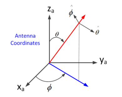
Since antennas have polarization, gain levels must be specified for the two orthogonal polarizations,  and
and  . The diagram below defines θ, ϕ, and the two associated polarization vectors that are implicit in the table.
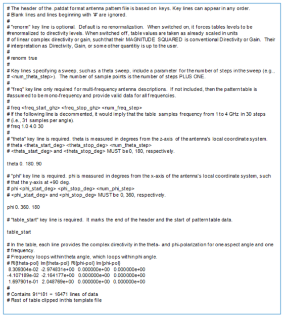
EMIT interprets the values in the *.patdat file as true antenna gain and uses these values in the EMI margin calculations. For this reason, the renorm flag is ignored if present in the *.patdat file and no normalization of the values to directivity is performed. The Ansys antenna pattern format is documented in the header comments in the example below.