
Circuit Getting Started Guides
Circuit documentation getting started guides provide step-by-step instructions on how to get started with the Circuit Design type of the Ansys Electronics Desktop. You will learn how to start Ansys Electronics Desktop, build basic designs, analyze the designs and generate reports showing the performance of those designs. You will also learn with the help of examples how to set up each of the design types, start the simulation, and perform post processing.
Circuit documentation includes the following Getting Started Guides:
- Getting Started with Circuit Design: Transmission Line, Mixer and Channel
-
Circuit Design Low Noise Amplifier Part 1
This two-part circuit design training manual describes a low noise amplifier design.
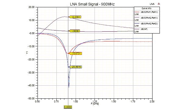
Part 1 of the guide shows how to use Circuit Design in the Ansys Electronics Desktop to design a small signal 900 MHz low noise amplifier (LNA) using an s-parameter model of NEC BJT NE68133, including noise parameters. The document also shows how to synthesize matching networks using the built-in Smith Tool. Tuned circuits are connected to the input and output to provide matching, essential to finalizing the design of the low noise amplifier.
-
Circuit Design Low Noise Amplifier Part 2
Part 2 covers the following topics:
- Circuit Simulation
- Schematic Capture
- DC Analysis
- Linear (S-parameter) Analysis
- Nonlinear Analysis
- Single Tone
- Compression
- Multi Tone
- Intermodulation
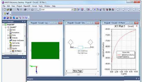
This guide provides step-by-step instructions on how to get started with the Circuit Design type of the Ansys Electronics Desktop. You will learn how to start Ansys Electronics Desktop, build basic designs, analyze the designs and report on the performance of those designs. You will also learn with the help of examples how to set up each of the design types, start the simulation, and perform post processing The examples include Basic Transmission Line, Simple Mixer and Simple Channel, and Low Pass Filter.
-
Getting Started Guide: Cable Modeling Solutions
The Ansys Electronics Desktop cable modeling solution is implemented using dynamic/data links between HFSS, 2D Extractor, and Circuit. A cable harness in HFSS is modeled as a single external field source based on quasi-static simulation of each cable cross-section in 2D Extractor and an analysis of the cable network in Circuit. The magnitude and distribution of the fields along each cable section is determined by the voltages and currents at the ends of each section, and then transmission line model is applied to propagate these fields along the cable length.
The solution include the following steps and data transfers:
- 2D Extractor
- solve the cable cross-section
- send a transmission line model for the cable network solution
- send transmission line modes and fields for the 3D cable solution
- Circuit
- define a step voltage on the appropriate ports on the circuit schematic
- solve the cable network
- send v and i at the ends of the cable for the 3D cable solution
- HFSS
- map fields onto the 3D cable, and solve the emissions from the cable assembly
- 2D Extractor