


Setting appropriate tolerances is critical to obtaining high quality mesh that adequately represents the geometry you want to capture.
The Tolerance value is used to find which mesh nodes on a body should be matched to mesh nodes on another body. Setting a larger Tolerance matches more nodes, while setting it smaller may cause some nodes not to be matched. For this reason, you might want to set this to a larger value than needed. Setting a smaller value can avoid problems in automatic contact matching, but can also result in other problems because the tolerance used in meshing is inherited from automatic contact match detection settings.
Considerations for Using a Large Tolerance Value
For a large assembly for which you do not want to define contact matches manually, automatic mesh contact match detection provides many benefits. Setting a large Tolerance value to find contact matches yields more matches.
However, larger values can be problematic. When more automatic contact matches are created, more duplicates can be created, which can cause problems when attempting to match the mesh. In general, making these decisions yourself is a better approach.
Considerations for Using a Small Tolerance Value
When contact matches are generated automatically, the Tolerance is used on the geometry edges and faces to determine which entities should be matched. However, the contact matches themselves are not generated until after the mesh has been generated. Because the contact matches are performed on nodes and elements of the mesh rather than on the geometry, the tolerances do not translate exactly.
For example, in the case below, you would want to set a Tolerance that is slightly larger than the gap in the geometry. If the gap is defined as x, and the tolerance is set to x, automatic mesh contact match detection could find the connection, but the meshing process may result in mesh that is only partially matched.

How the Tolerance Affects Gaps and Boundaries
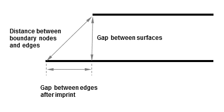
The tolerance also controls how the mesh nodes are matched when there is a gap between the boundary edges of the "Primary" and "Secondary" bodies, or a gap between the bodies themselves, or both.
The following figure shows how the tolerance can be used to match mesh nodes between two solid bodies. In this example, there is a gap between the bodies, as well as a gap between the boundary edges.
Assuming that the mesh size is not too large, the following table describes how the mesh will be matched when there are gaps between bodies and boundaries:
Table 4: Mesh Matching for Gaps
| If... | Then... |
|---|---|
| There is a gap between the bodies only | The mesh is matched between the bodies as long as the gap between surfaces is within the specified tolerance. The gap will remain, but the mesh nodes will be matched. |
| There is a gap between the boundary edges, but not between the bodies |
This mesh is generated first, and the parts are meshed separately. The gap may be meshed depending on the mesh sizes being used and whether there is an imprint in the geometry. Note: If there is an imprint in the geometry and you want to remove the gap, you can remove it by inserting a pinch control prior to meshing. For more information, see Pinch Control. |
| There is a gap between both the bodies and the boundary edges | The mesh is matched along the boundaries as long as the gap is within the specified tolerance, and the mesh size is less than or equal to the size of the gap. If the gap is not within the tolerance, or if the mesh size is too large, then the mesh is matched from the edge to the interior. |
The mesh size also affects how the mesh is matched for these types of bodies. For more information, see How Mesh Size Affects Contact Matches.