Nine blades and nine splitter blades are displayed.
Now that the geometry has been loaded in BladeEditor, you can modify it. Instructions for doing this are provided in the following sections:
In this section, you will change the shroud in various places. Some of these changes will affect the geometries of the main blade and splitter blade.
Modify the meridional sketch at the shroud as follows:
In the Tree Outline view, right-click
Blade1and select Suppress & All Below.This is done so that sketches can be seen clearly without the geometry obstructing your view.
As an alternative to suppressing the blade, you can click Display Model
 to toggle the visibility of the blade.
Hide the Angle and Thickness views by clicking the Show/Hide Angle Pane
 and Show/Hide Thickness Pane
  toolbar icons respectively.
Select the Sketching tab at the bottom of the Tree Outline view to switch to the Sketching Toolboxes.
Click Look At Face/Plane/Sketch
 and zoom in as
appropriate.
and zoom in as
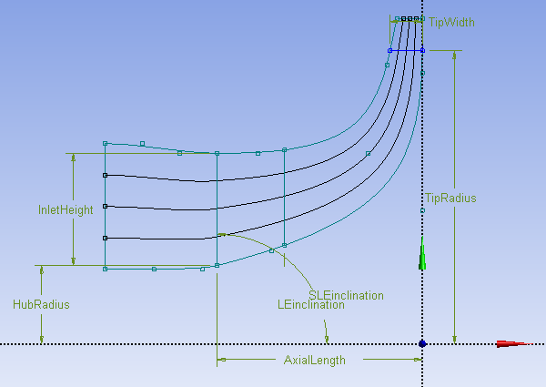
appropriate.You should see the following sketch in the graphics view:

Select TipRadius in the 3D Viewer.
In the details view for TipRadius, change Value to
6 cm.Select InletHeight.
In the details view for InletHeight, change Reference Only? to
Yes.InletHeight no longer governs the control point at the blade leading edge on the shroud.
In the Modify toolbox, select Drag.
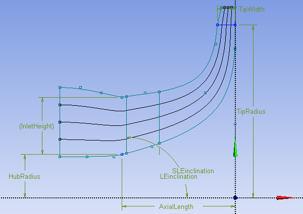
Using the mouse, drag the control point at the blade leading edge on the shroud downward and rightward a short distance.
Click Generate
 .
.The upstream portion of the shroud curve, as well as the curves on the other layers, are modified as a result.

Select InletHeight.
In the details view for InletHeight, change Reference Only? to
No.InletHeight now governs the control point at the blade leading edge on the shroud.
Note: Note that you could have caused the same modification by leaving InletHeight as a dimension (Reference Only? set to
No) and changing its value in the details view.Changing a key dimension, such as InletHeight, usually causes multiple control points to move. This technique enables you to make large changes to the geometry quickly.
Select the Modeling tab.
In the Tree Outline view, right-click
Blade1and select Unsuppress & All Below.
Blade Comparison mode enables you to create a snapshot of the blade. After you create the snapshot, you can make changes to the blade and then compare the current version of the blade to the snapshot.
In this section, you will:
Take a snapshot of the blade
Modify the blade angle
Modify a control point on the shroud
View the changes you have made
Start Blade Comparison mode.
Click Create snapshot
 .
.A snapshot of the blade in its current state is now stored in BladeEditor.
Note that BladeEditor can only create a snapshot when the FlowPath, Blade, and Splitter features have been successfully generated.
Click Display Model
 to hide the geometry.
 This is done so that the modifications made to the blade can be seen clearly.
Click Comparison On/Off
 to toggle the visibility of the snapshot.
Modify the blade angle.
In the Tree Outline, select
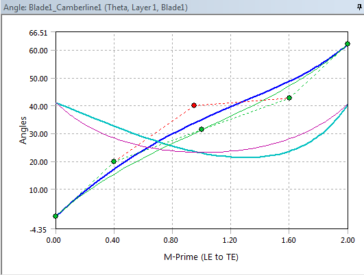
Blade1>Blade1_Camberline1In the Angle view, drag a control point to change the shape of the curve.

Note that Blade Comparison mode shows you the shape of the curve from the snapshot as well as the present shape of the curve.
Modify a shroud control point as follows:
Select the Sketching tab.
In the Modify toolbox, select Drag.
Using the mouse, drag a point on the shroud a short distance.
Note: Instead of dragging the point, you can cause the same
modification by making the point a dimension (Reference
Only? set to No) and changing its
value in the details view.
Click Generate ![]() to compare the snapshot of the geometry to the present geometry
in the 3D Viewer.
to compare the snapshot of the geometry to the present geometry
in the 3D Viewer.
After the geometry has been generated, you are able to view the differences between the snapshot (shown in pink) and the present geometry. Note that you may have to rotate the geometry and zoom in to see the differences in the geometry.
Click Comparison On/Off  to turn off Blade Comparison mode.
Note: To control the snapshot display settings in Blade Comparison
mode, click Comparison display option .
.
Generate and view the blade row, then reduce the number of blade sets to seven.
On the Modeling tab, select
Blade1.In the Details view for
Blade1, change FD1, Number of Blade Sets to7.Click Generate
 .
.
There are now seven main blades and seven splitter blades.
Adjust the shape of the leading edge of the main blade.
In the Details view for
Blade1, ensure that Leading Edge Details > Type is set toEllipse.Set FD2, Ellipse Ratio at Hub to
1.5.Set FD3, Ellipse Ratio at Shroud to
1.0.Click Generate
 .
.
Note: You can adjust the leading edge of the splitter blade in the same way.
In this section you will:
Add a new layer at a constant span fraction value and use it to add a new camberline/thickness definition subfeature to the main blade and also the splitter blade.
Add a user-defined layer (which involves using a sketch to define the layer) and use it to add a new camberline/thickness definition subfeature to the main blade.
Specify that the angle data and thickness data of the camberline/thickness definition on the user-defined layer are interpolated from camberline/thickness definitions on surrounding layers.
Insert a new layer and camberline/thickness definition and interpolate it from the existing layers:
In the Tree Outline view, select
FlowPath1.The Details view for
FlowPath1is displayed.Right-click Layer Details: 2 and select Insert Layer Above.
Set Span Fraction 2 to
0.2.Click Generate
 .
.The new layer is now ready to be used by any of the blades.
In the Tree Outline view, select
Blade1.Note that the tree shows five camberline sub-features under
Blade1. Although you have added a layer to the flowpath used by the blade, the layer is not initially being used to define a camberline/thickness definition.In the details view for
Blade1, under Camberline/Thickness Definitions, set Layer 2 toYes.This causes a camberline/thickness definition to be created on that layer, as can be confirmed in the tree view, which now shows six camberline sub-features under
Blade1.In the details view for
Splitter1, under Camberline/Thickness Definitions, set Layer 2 toYes.This causes a camberline/thickness definition to be created on that layer, as can be confirmed in the tree view, which now shows six camberline sub-features under
Splitter1.Click Generate
 .
.
Create a sketch to be used in the definition of a user-defined layer:
In the Tree Outline view, right-click
Blade1and select Suppress & All Below.This is done so that sketches can be seen clearly without the geometry obstructing your view.
Select
MerPlane1in the Tree Outline view.Click New Sketch
 .
.A new sketch,
Sketch11, appears in the Tree Outline view underMerPlane1.Ensure that
Sketch11is selected in the Tree Outline view.Select the Sketching tab at the bottom of the Tree Outline view to switch to the Sketching Toolboxes.
Click Look At Face/Plane/Sketch
 and zoom in as
appropriate.
and zoom in as
appropriate.Draw an open-ended curve (for example, a line, polyline, spline, or combination thereof) that passes through the blade passage from inlet to outlet, between the previously-added layer and the shroud, without crossing any existing layers.
If you use more than one curve to produce a chain of curves, test that the chain is unbroken.
Next, use the sketch to create a user-defined layer:
On the Modeling tab, right-click
FlowPath1and select Edit Selections.Click
Sketch11in the tree view, then, in the details view, click the field beside Sketches for Defined Layer, then click Apply.Click Generate
 .
.A new layer appears in the Layer Details portion of the details pane.
The span fraction value is an average of the span value over the sketch used to define the layer.
Next, make a camberline/thickness definition for Blade1 using the user-defined layer:
In the Tree Outline view, select
Blade1.Note that the tree shows six camberline sub-features under
Blade1. Although you have added a layer to the flowpath used by the blade, the layer is not initially being used to define a camberline/thickness definition.In the details view for
Blade1, under Camberline/Thickness Definitions, set the layer you previously created toYes.This causes a camberline/thickness definition to be created on that layer, as can be confirmed in the tree view, which now shows seven camberline sub-features under
Blade1.
Next, make the angle and thickness data on the user-defined layer non-editable, so that it is always interpolated:
In the Tree Outline under
Blade1, select the camberline subfeature that corresponds to the layer that you previously created.In the details view, set Angle Definition and Thickness Definition to
Interpolated.This makes the Angle view and Thickness view read-only. Angle data and thickness data are now interpolated from camberline/thickness definitions on surrounding layers. The control points disappear from the angle graph and from the thickness graph.
On the Modeling tab, right-click
Blade1in the Tree Outline view and select Unsuppress & All Below.The blade row should be displayed.
Note: If you wanted to add more user-defined layers, you could add more sketch curves by doing either or both of the following:
Add more curves to an existing sketch that is already used by the FlowPath feature to define at least one layer.
Create new sketches, and then add them to the FlowPath feature as sketches to be used for layers (under the Sketches for Defined Layer property).
Remember that, before you can add sketches to the FlowPath feature, you must right-click the FlowPath feature in the Tree Outline view and select Edit Selections.


