Input parameters for steering, braking and acceleration are described for each scenario. It is assumed that customers have dynamic vehicle models ready to run the scenario.
Vehicle control inputs are categorized as follows:
Open-loop steering
Cornering
Straight-line
Within each category, specific scenarios are available as listed in the table below.
| Analysis Category | Analysis Type |
| Open-loop steering | Drift |
| Fish Hook | |
| Impulse Steer | |
| Ramp Steer | |
| Single Lane Change | |
| Step Steer | |
| Swept Sine Steer | |
| Cornering | Braking-in-Turn |
| Constant Radius Cornering | |
| Cornering with Steer Release | |
| Lift-off Turn-in | |
| Power-off Cornering | |
| Straight-line | Acceleration |
| Braking | |
| Power-off Straight Line |
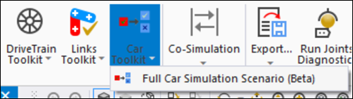
To define a vehicle simulation scenario, you need to insert a object from the category.
The object requires scenario inputs to simulate the vehicle.
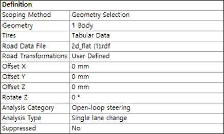
Each input is grouped as shown in the Definition panel above.
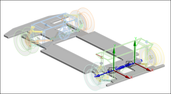
You must select a body (chassis in this case) from which vehicle position, velocity, and acceleration are evaluated and reported. Position (displacement) results are calculated with reference to the global inertia reference marker. Velocities and accelerations of the chassis are calculated at the mass center marker of the moving body. The body side-slip angle is the angle between the vehicle's direction of motion and the longitudinal direction. The side-slip angle is defined as positive when the vehicle rotates in the counterclockwise direction.
 | (2–1) |
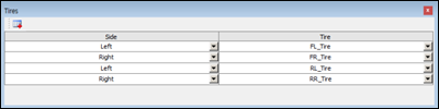
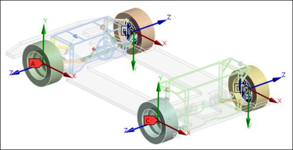
The tire rotation axis is defined in the outboard direction. Mechanical Motion requires definitions for the location of each tire (left or right).
This parameter specifies the road data file for the vehicle simulation scenario. A road file is defined in conjunction with a tire. When the full vehicle simulation scenario needs a new road profile for simulation, the road file defined with the tire gets deactivated. The deactivated road file can be re-activated when a full car simulation scenario is suppressed or deleted.
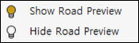
You can toggle the display of the road surface profile using the Show / Hide Road Preview options from the context-sensitive menu for the simulation scenario object (see below).
You can use a transformation function to position the road with the required coordinates and orientation. The road is transformed relative to the reference frame, the orientation of which is the same as that of the global coordinate system.
The position of the reference frame is determined as follows:
X = the x-coordinate of the front tires.
Y = 0
Z = the lowest tire patch z location among front and rear tires.
For example, these tire parameters,
Unloaded tire radius: 317.25 mm
Front left tire: {50 mm, 600 mm, 350 mm}
Front right tire: {50 mm, -600 mm, 350 mm}
Rear left tire: {2800 mm, 600 mm, 370 mm}
Rear right tire: {2800 mm, -600 mm, 370 mm}
result in the following reference frame definition,
Origin X: 50 mm
Origin Y: 0 mm
Origin Z: 32.75 mm
X Axis [1. 0. 0.]
Y Axis [0. 1. 0.]
Z Axis [0. 0. 1.]
Parameters used to define a road transformation are as follows:
- Road Transformations
Either or . For the option, the properties for the transformation (offset and rotation) will be displayed as described below.
- Offset X
The offset of the road in the x-axis direction of the reference frame.
- Offset Y
The offset of the road in the y-axis direction of the reference frame.
- Offset Z
The offset of the road in the z-axis direction of the reference frame.
- Rotate Z
The rotation angle of the road about the z-axis of the reference frame.
There are three steering input categories (, , and ) for vehicle simulation. Open-loop steering analyzes vehicle behavior under a pre-defined steering input. Cornering analysis allows simulation of combined cornering events, which include in a corner, in a corner, in a corner, while cornering and cornering. Straight-line analysis scenarios consider the vehicle travelling in a straight line.
The analysis type can be set to either , , or . Each analysis type requires inputs to define a driving scenario. Refer to Detailed Input Parameters for a Driving Scenario for more information.
A Steering System must be specified to define steering inputs.
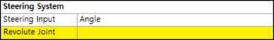
Steering System parameters are as follows:
- Steering Input
The steering input can be specified as either or . The angle input is applied to the steering wheel, while the length option controls the rack in the steering system and the input is applied to the translational motion between the rack and the steering gear housing. A positive steering input should make the vehicle turn left.
- Revolute Joint
The Revolute Joint between the steering wheel and the body when Steering Input is set to .
- Translational Joint
The Translational Joint between the rack and the steering gear when Steering Input is set to .
All driving scenarios need a Powertrain System, which defines a revolute joint for transmitting the axle torque. A positive powertrain input (torque) makes the vehicle move forward.
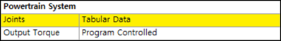
Define the left and right revolute Joints to transmit the engine torque using . The joints should be defined in the same rotational direction so as to drive the car forward under engine torque in the positive direction.
The options to define the Output Torque are as follows:
- Program Controlled
The default option to calculate the engine output torque in the program. Engine, transmission and axle torques are generated from the powertrain data. You are encouraged to use your own data for specific applications.
- User Defined
Allows you to define each individual parameter that is used in the calculation of the engine output torque, such as the Torque Map File, Clutch, Engine, Gear Input, and Final Drive.
- Function Expression
This option defines the left and right output torque through user-defined functions.
A Brake System is required for braking scenarios and defines the revolute Joints for braking. Braking torque in the positive direction of the joint will make the vehicle decelerate.
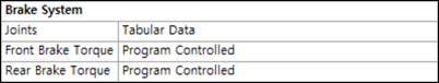
Define the front, rear, left and right revolute joints to transmit the brake torque using . The axis of rotation of these joints should be set to or based on the vehicle driving direction.
The following options can be used to define the Brake Torque for front and rear wheels:
- Program Controlled
The default option to calculate the brake torque in the program. With this option, the brake torque is applied without any additional input from the user.
- User Defined
Use this option to define each individual parameter used in the calculation of the brake torque, such as Brake Bias, Piston Area, and Brake mu.
- Function Expression
This option defines the brake torque through user-defined functions.
Parameters for a driving scenario are split into the following analysis categories:
Note: For most Analysis Types (except and ), Cruise Control is applied. This means that the Initial Velocity input for the vehicle is maintained throughout the entire simulation period.
|
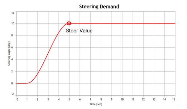
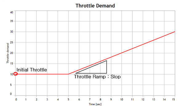
Drift: This is an analysis in which steering is applied to the vehicle bewteen the 1 and 5 second marks in order to achieve a steady-state cornering condition. A powertrain ramp input is then applied. The figures below show the throttle and steering demand for each parameter input.
| |
| Property | Description |
| Initial Velocity | The initial velocity of the vehicle. |
| Initial Throttle | The initial throttle value of the powertrain. The throttle value remains constant for 5 seconds. A ramp input is then applied. |
| Throttle Ramp | Defines the rate of throttle change. |
| Steer Value | The steering input value at the 5 second mark. The steering input is a step function changing from zero to this value, over a 5 second period. |
| Gear Position | The initial gear position of the powertrain. |
|
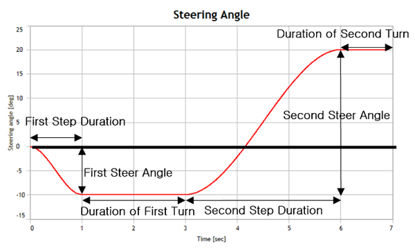
Fish Hook: This is an analysis that evaluates the stability of the vehicle in a roll-over event. The steering wheel inputs are step functions. In the figure below, the first turn is a step function for the right turn and the second for the left turn. The major outputs from this analysis are steering wheel angle, lateral acceleration, yaw rate, and roll angle. The figure below shows steering wheel angle vs time and the associated input parameters.
| |
| Property | Description |
| Initial Velocity | The initial velocity of the vehicle. |
| First Turn Direction | The first turn steering direction. Left corresponds to the positive direction of the Joint in the Steering System. |
| First Steer Angle | The maximum steering value in the first turn. |
| First Step Duration | The duration of the first steering step. |
| Duration of First Turn | The duration that the final value of the first steering input is maintained. |
| Second Turn Direction | This defines the second turn steering direction. Right corresponds to the negative direction of the Joint in the Steering System. |
| Second Steer Angle | The total steering value deflection during the second steering step. |
| Second Steering Duration | This defines the duration of the second steering step. |
| Duration of Second Turn | The duration that the final value of the second steering input is maintained. |
| Gear Position | The initial gear position of the powertrain. |
|
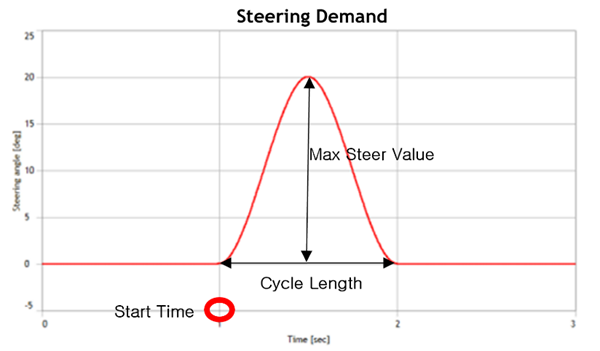
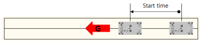
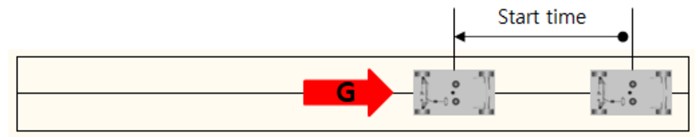
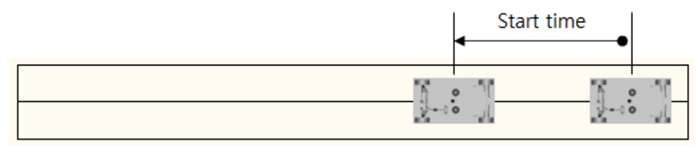
Impulse Steer: This is an analysis in which an impulse steering input ( or ) is applied to the vehicle system. The figure below shows an example of steering demand and associated input parameters.
| |
| Property | Description |
| Initial Velocity | The initial velocity of the vehicle. |
| Start Time | The start time of the steering impulse. |
| Cycle Length | The total duration of the steering impulse. |
| Maximum Steer Value | The maximum steering value of the steering impulse. |
| Gear Position | The initial gear position of the powertrain. |
|
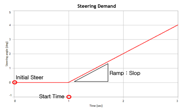
Ramp Steer: This is an analysis in which the steering input ( or ) is a ramp function. The figure below shows the steering demand and associated input parameters.
| |
| Property | Description |
| Initial Velocity | The initial velocity of the vehicle. |
| Start Time | The time when the Ramp Steer starts. |
| Ramp | The rate of change of the steering value. |
| Initial Steer Value | The initial steering value. |
| Gear Position | The initial gear position of the powertrain. |
|
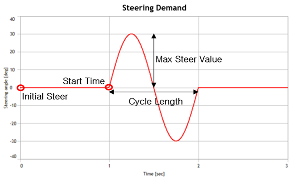
Single Lane Change: This is an analysis in which the steering input ( or ) is a sine function. The figure below shows the steering input and associated input parameters.
| |
| Property | Description |
| Initial Velocity | The initial velocity of the vehicle. |
| Start Time | The time when the Single Lane Change starts. |
| Cycle Length | The total duration of the Single Lane Change input. |
| Initial Steer Value | The initial steering value. |
| Maximum Steer Value | The maximum steering value during the Single Lane Change. |
| Gear Position | The initial gear position of the powertrain. |
|
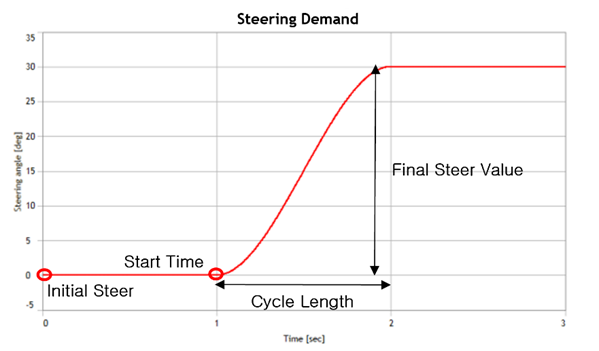
Step Steer: This is an analysis in which the steering input ( or ) is a step function. The figure below shows the steering demand and associated input parameters.
| |
| Property | Description |
| Initial Velocity | The initial velocity of the vehicle. |
| Step Start Time | The time when the Step Steer starts. |
| Duration of Step | The duration of the Step transition. |
| Initial Steer Value | The initial steering value. |
| Final Steer Value | The final steering value of the Step Steer |
| Gear Position | The initial gear position of the powertrain. |
|
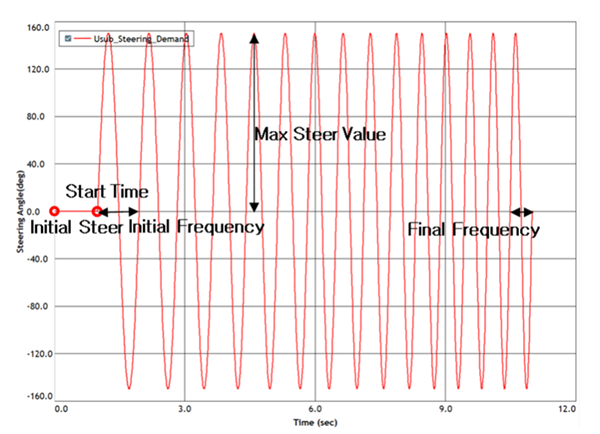
Swept Sine Steer: In this analysis, the steering input is composed of sine functions of varying frequencies where the sweep frequency increases at a given rate. The figure below shows the steering demand and associated input parameters.
| |
| Property | Description |
| Initial Velocity | The initial velocity of the vehicle. |
| Start Time | The time when the Swept Sine Steer starts. |
| Initial Frequency | The initial frequency |
| Maximum Frequency | The final frequency |
| Frequency Rate | The rate of frequency change. |
| Initial Steer Value | The initial steering value. |
| Maximum Steer Value | The maximum steering value |
| Gear Position | The initial gear position of the powertrain. |
|
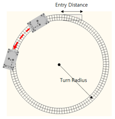
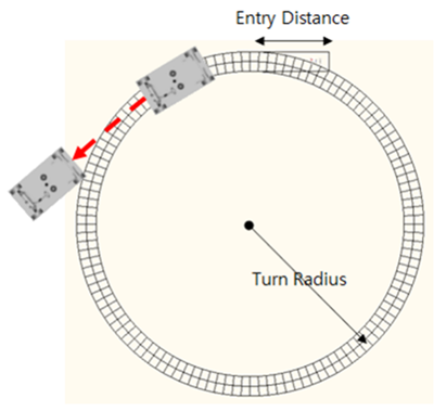
Braking in Turn: This analysis applies a braking input to the vehicle while the vehicle is in a steady-state circle turn. Once the vehicle reaches a target lateral acceleration during cornering, a brake input is applied. The tire model requires proper friction circle characteristics for a reasonable analysis. This is a long event, so enter a suitable end time (for example 100s) in the Analysis Settings. The analysis is automatically terminated after Maximum Brake Duration since the start of the steady-state circle turn.
| |
| Property | Description |
| Lateral Acceleration | The target lateral acceleration before the brake input is applied. |
| Turn Radius | The radius of the circle turn. |
| Turn Direction | The turn direction. For a left turn, a positive input motion is applied to the steering joint. Ensure that a positive motion makes the vehicle turn left. |
| Steering Condition |
Steering condition during braking: - the steering joint is locked during braking. - the steering is controlled to maintain the circle turn during braking. |
| Brake Deceleration | The target longitudinal deceleration in the user-specified unit for the brake event. |
| Maximum Brake Duration | The braking duration. The simulation terminates after this period. |
| Entry Distance | The initial straight-line running distance of vehicle before cornering. |
| Settle Time | N/A |
| Gear Position | The initial gear position of the powertrain. |
|
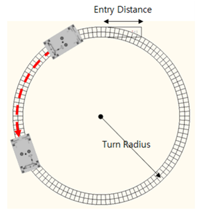
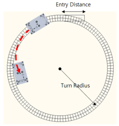
Constant Radius Cornering: In this analysis, the vehicle is in a steady-state circle turn and then accelerates (increasing the driving speed while the vehicle is moving with a defined turning radius). The vehicle velocity traveling within a specified radius is increased when its velocity reaches the Initial Velocity or Initial Lateral Acceleration. In the Duration of Maneuver, the velocity is increased to either Final Velocity or Final Lateral Acceleration. The steering input to maintain the cornering is controlled with velocity. The tire model requires proper friction circle characteristics for a reasonable analysis. This is a long event, so enter a suitable end time (for example 100s) in the Analysis Settings. The analysis is automatically terminated after Duration of Maneuver since the start of the steady-state circle turn.
| |
| Property | Description |
| Turn Radius | The radius of the circle turn. |
| Turn Direction | The direction of the turn ( or ). A positive steering input makes the vehicle turn left. |
| Control |
The acceleration control option: : The initial and final velocity for acceleration are direct inputs. : The initial velocity and the final velocity for acceleration are calculated by lateral acceleration. |
| Duration of Maneuver | The duration of the velocity change from the initial velocity to the final velocity. The simulation is terminated after this duration. |
| Initial Velocity | The initial velocity before accelerating. |
| Final Velocity | The final velocity when the acceleration is completed. |
| Initial Lateral Acceleration | Lateral acceleration of the initial velocity. |
| Final Lateral Acceleration | Lateral acceleration of the final velocity. |
| Shift Gears | This defines whether the gear is shifted or fixed. |
| Entry Distance | The initial straight-line distance before the vehicle starts cornering. |
| Settle Time | N/A |
| Gear Position | The initial gear position of the powertrain. |
|
Cornering with Steer Release: The steering wheel is released once the vehicle is in a steady-state circle turn. After the steering wheel is released, the steering input becomes zero for 5 seconds while driving at a constant velocity. This is a long event, so enter a suitable end time (for example 100s) in the Analysis Settings. The analysis is automatically terminated 5 seconds after Steer Release.
| |
| Property | Description |
| Turn Direction | The direction of the turn ( or ). A positive steering input makes the vehicle turn left. |
| Steady-State Prephase |
This is the option to define turn radius: : The turn radius is a direct input. : The turn radius is calculated by (lateral) acceleration. |
| Turn Radius | Turn radius when the Steady-State Prephase option is set to . |
| Lateral Acceleration | Lateral acceleration when the Steady-State Prephase option is set to . This can be used to calculate the turn radius and the longitudinal velocity. |
| Longitudinal Velocity | The longitudinal velocity during cornering. |
| Entry Distance | The initial straight-line distance before the vehicle starts cornering. |
| Settle Time | N/A |
| Gear Position | The initial gear position of the powertrain. |
|
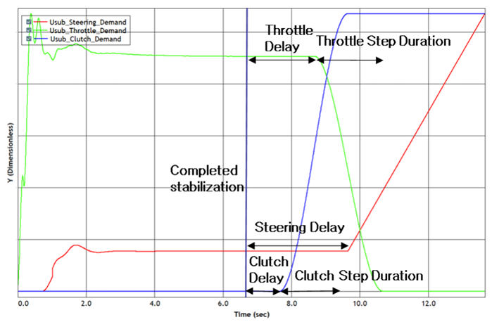
Lift-off Turn-in: This is an analysis where a ramp steering input is applied with the throttle off in a steady-state circle turn. The steering input increases at the rate of the steering ramp for 5 seconds with the throttle off. This is a long event, so enter a suitable end time (for example 100s) in the Analysis Settings. The analysis is automatically terminated 5 seconds after Lift-off.
| |
| Property | Description |
| Lateral Acceleration | Lateral acceleration of the vehicle in the circle turn. This value determines the velocity of the vehicle. |
| Turn Radius | The radius of the circle turn. |
| Turn Direction | The turn direction ( or ). A positive steering input makes the vehicle turn left. |
| Steering Delay | The time delay from the steady-state circle turn before applying the steering ramp input. |
| Steering Ramp | The rate of steering input increase. |
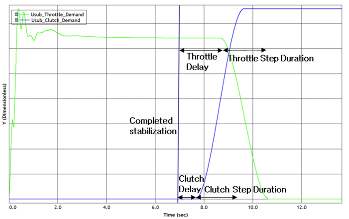
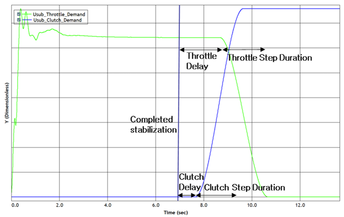
| Throttle Delay | The time delay from the steady-state circle turn before the throttle input is removed. |
| Throttle Step Duration | The time for the throttle value to decrease to zero. |
| Disengage Clutch During Lift Off | Select this option to disengage the clutch during lift-off. |
| Clutch Delay | The time delay before the clutch starts to disengage. |
| Clutch Step Duration | The time taken for the clutch to disengage. |
| Entry Distance | The initial straight-line distance before the vehicle starts cornering. |
| Settle Time | N/A |
| Gear Position | The initial gear position of the powertrain. |
|
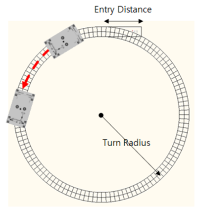
Power-off Cornering: This is an event in which the throttle input and the clutch are disengaged with a step function while the vehicle is in a steady-state circle turn. This is a long event, so enter a suitable end time (for example 100s) in the Analysis Settings. The analysis is automatically terminated 5 seconds after Power-off.
| |
| Property | Description |
| Lateral Acceleration | Lateral acceleration of the vehicle during cornering. This value determines the velocity of the vehicle. |
| Turn Radius | The radius of the circle turn. |
| Steering Condition |
There are two options for the steering input: : The steering input is fixed. : The steering input is controlled to maintain the turn radius. |
| Turn Direction | The turn direction ( or ). A positive steering input makes the vehicle turn left. |
| Throttle Delay | The time delay from the steady-state circle turn before the throttle is disengaged. |
| Throttle Step Duration | The time for the throttle value to become zero. |
| Disengage Clutch During Power Off | Option to disengage the clutch during power-off |
| Clutch Delay | The time delay from the steady-state circle turn before the clutch starts to dis-engage. |
| Clutch Step Duration | The time taken for the clutch to disengage. |
| Entry Distance | The initial straight-line distance before the vehicle starts cornering. |
| Settle Time | N/A |
| Gear Position | The initial gear position of the powertrain. |
|
Acceleration: This is an analysis of increasing the vehicle speed according to a defined condition while driving in a straight line. The acceleration condition includes open loop and closed loop options. In an open loop, the throttle demand increases from zero to the final condition defined by the user. In a closed loop, the throttle demand is controlled until the vehicle reaches the target acceleration. Available steering conditions are , , and .
| |
| Property | Description |
| Initial Velocity | The initial velocity of vehicle. |
| Start Time | The time during which the vehicle is accelerating. |
| Throttle Loop Type |
This defines the acceleration type: : Accelerated by the throttle condition. : Pre-defined longitudinal vehicle acceleration. |
| Final Throttle | This defines the final throttle for the condition when the throttle input is a step function. |
| Duration of Step | The duration of the throttle operation. |
| Longitudinal Acceleration | The desired longitudinal acceleration for control. |
| Steering Condition |
The option for steering input: : Steering is controlled to keep the vehicle in a straight line. : Steering input is unlocked and moves freely by external load. : The steering joint is fixed during braking. |
| Shift Gears | Defines whether the gear is shifted or fixed. |
| Gear Position | The initial gear position of the powertrain. |
|
Braking: This is a straight-line braking analysis. Braking is applied via either open loop or closed loop control. In an open loop, the brake demand increases from zero to the final brake value. In a closed loop, the brake demand is controlled until the target deceleration is reached. The steering can be defined as , , or .
| |
| Property | Description |
| Initial Velocity | The initial velocity of vehicle. |
| Start Time | The time when the brake is applied. |
| Brake Loop Type |
This defines the braking type: : The brake input is a function of time. Closed-Loop Brake: The braking is defined by the target deceleration. |
| Final Brake | This defines the final brake value for the condition. |
| Duration of Step | The time taken to reach the final brake value. |
| Longitudinal Deceleration | The target longitudinal deceleration for the brake event. |
| Steering Condition |
This option defines the steering type during braking: : The steering input keeps the vehicle in the straight line. : The steering joint is unlocked and moves freely by external load. : The steering joint is fixed during braking. |
| Gear Position | The initial gear position of the powertrain. |
|
Power-off Straight Line: This is an analysis to assess the vehicle's path deviation when the throttle is off while the vehicle is driving straight. The vehicle undergoes Power-off after the Start Time.
| |
| Property | Description |
| Initial Velocity | This defines the initial velocity of vehicle. Rotational velocities of the tires are defined with this value. |
| Start Time | The time when the throttle input is removed. |
| Straight Line Control |
This option controls the steering during power-off: : Steering is controlled to make the vehicle drive straight. : Steering is fixed with a specified steering input. |
| SWA | The steering wheel angle when the Straight Line Control option is set to . |
| Throttle Delay | The time delay from the steady-state state straight-line run before the throttle input is removed. |
| Throttle Step Duration | The time taken for the throttle value to reach zero. |
| Disengage Clutch During Power Off | Select this option to disengage the clutch during power-off. |
| Clutch Delay | The time delay from the steady-state straight-line run before the clutch starts to disengage. |
| Clutch Step Duration | The time taken for the clutch to disengage. |
| Gear Position | The initial gear position of the powertrain. |
A vehicle simulation produces a lot of data, including position, velocity, acceleration, and side-slip in the longitudinal, lateral, vertical, roll, yaw, and pitch directions of the vehicle. This section introduces how to post-process these outputs.
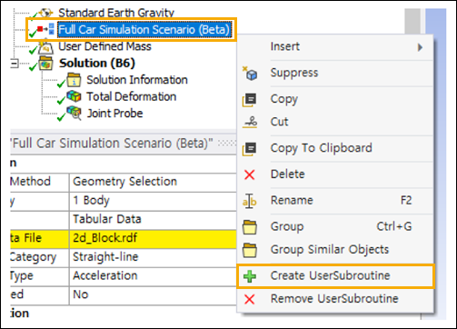
Before running a vehicle simulation, define the User Subroutine objects to be used for the car simulations. These should be defined using the Create User Subroutine option in the context-sensitive menu for the Full Car Simulation Scenario.
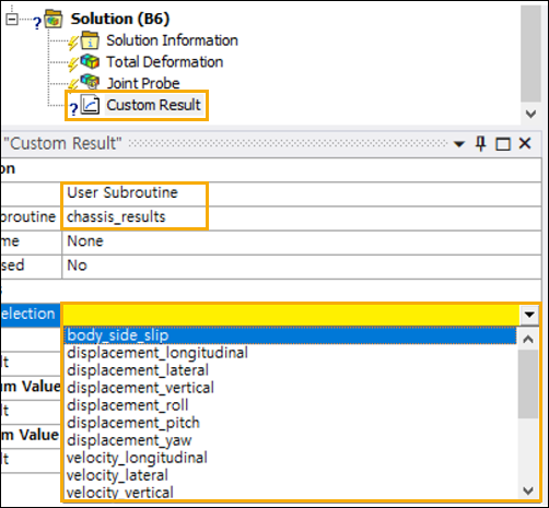
Insert a Custom Result object in the Solution.
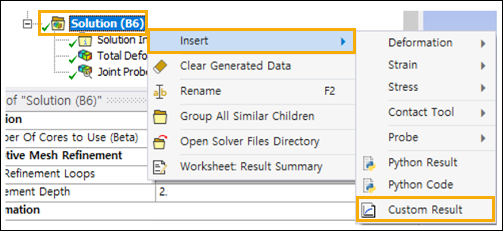
For each Custom Result, you need to set the
Type to and select the
User Subroutine object created by the previous action. The user
subroutine name is chassis_results by default.