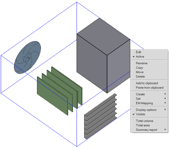
You can access a context menu in the Graphics display window by holding down the Shift key and the right mouse button near the edges of an object or on a postprocessing legend. The context menu allows you to quickly perform common tasks on the objects in your model. Context menu options may be slightly different depending on the type of object selected.
Note: If Set <Shift-RightClick> to object menu is not enabled in the Preferences tab, the context menu will not appear for an object. Instead, the interactive object resize feature will be enabled. See Changing the Mouse Controls for more details.
The Graphics display context menu includes the following options:
Edit allows you to edit the properties of the item.
Active allows you to toggle the item's activity.
Rename allows you to rename the selected object.
Copy allows you to copy the selected object.
Move allows you to move the selected object.
Delete moves the item to the Trash node.
Add to clipboard copies the item to the clipboard. See page Using the Clipboard for more information about the clipboard.
Paste from clipboard pastes the item from the clipboard to your model. See page Using the Clipboard for more information about the clipboard.
Create allows you to create an assembly, group, monitor point, monitor surface, or object face from the selected item.
Assembly allows you to create an assembly from the selected item.
Group allows you to create a group from the selected item.
Monitor point allows you to create monitor points for selected objects. This will also copy the selected objects from the Model node into the Points node. See Defining Solution Monitors for more information on object monitor points.
Monitor surface allows you to create monitor surfaces for selected objects. This will also copy the selected objects from the Model node into the Surfaces node. See Defining Solution Monitorsfor more information on object monitor surfaces.
Object face(s) allows you to create object faces for selected objects. Newly created object faces will show up under the Post-processing node. See Displaying Results on Object Faces for more information on defining object faces.
Set allows you to set multi-level meshing levels, object mesh parameters, object zone merge settings, and solar participation settings.
Multi-level meshing level opens up the Multi-level meshing level panel where you can enter the multi-level meshing maximum level. See Global Refinement for a Hex-Dominant Mesh for more information on editing levels.
Object mesh params opens up the Per-object parameters panel where you can review and define meshing parameters specific to the selected object. See General Procedure for more information on defining object-specific meshing parameters.
Object zones merge opens up the Merge object zones panel where you can turn off zone merging for an object or groups of objects. By default the option Don't merge object zones is off. This option has the effect of writing a separate zone for each of the selected object(s) in the solver to enable the specification of certain boundary conditions. If this option is turned on, the Merge zones when possible option in the Solve panel should be turned on to turn off zone merging for that object(s). This option cannot be used for Cabinet, assemblies, or materials.
Solar particpation opens up the Solar loading panel. By default, when Solar loading is enabled on the Basic parameters Advanced tab, the option Participate in solar loading is turned on. If this option is turned off for a given object, the object does not participate in solar loading.
EM Mapping allows you to open the Volumetric heat losses panel or Surface heat losses panel. Only the object selected in the Model Display window appears in the list.
Note: To display all objects of an assembly in the panel, select the assembly and one of its member objects in the Model Display window, right-click the selected member object in the Model manager, and select EM Mapping and then Volumetric heat loss or Surface heat loss.
Display options allows you to Set shading and/or Set transparency for objects. See Graphical Style for more information on displaying graphical style options.
Visible allows you to toggle the item's visibility. Hidden object appear in the Model manager window as grayed out items and are visible in the graphics window. This allows you to view and edit portions of your model while hiding the rest.
Total volume prints the total volume of selected objects (excluding CAD objects) in the Message window.
Total area prints the total area of selected objects (excluding CAD objects) in the Message window.
Summary report opens the Define summary report panel where you can specify a summary report for a variable on any or all objects in your Ansys Icepak model. See Summary Reports for more information on creating a summary report.
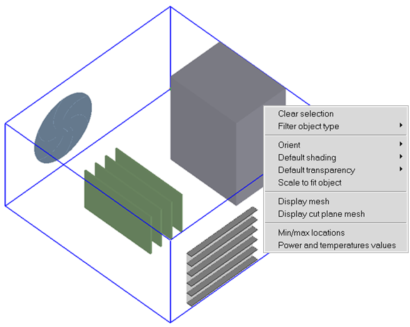
You can access another context menu in the Graphics display window by holding down the Shift key and the right mouse button anywhere in the Graphics display window away from the edges of objects or post processing objects. The context menu allows you to quickly perform common tasks in your model.
The Graphics display context menu includes the following options:
Clear Selection allows you to remove all selected objects in the graphics window.
Filter object type allows filtering of objects by object type from a preselected list of objects.
Orient allows you to modify the direction from which you view your model. Besides selecting the view along the x, y, and z axis, you can scale it to fit exactly within the graphics window.
Isometric views the model from the direction of the vector equidistant to all three axes.
Scale to fit model adjusts the overall size of your model to take maximum advantage of the graphics width and height.
Orient positive x, y, z views the model toward the direction of the positive x, y, or z axis.
Orient negative x, y, z views the model toward the direction of the negative x, y, or z axis.
Default shading allows options that control the rendering of your Ansys Icepak model.
Wire outlines the model's outer edges and those of its components.
Solid adds solid-tone shading to the visible surfaces of the model's internal components to give them a solid appearance.
Solid/wire adds solid-tone shading to the visible surfaces of the object currently selected in the object Edit window to give it a solid appearance. Also, an outline of the surfaces will be displayed in either white or black depending on the background color.
Hidden Line activates the hidden line removal algorithm, which makes objects that are drawn to look transparent now appear to be solid.
Selected solid highlights selected objects to give them a solid appearance. If Solid fill is selected in the mesh Display tab, then the solid fill color of the mesh will take precedent. Otherwise this option overrides all previous object display settings.
Default transparency allows options that control the transparency of your Ansys Icepak model.
Scale to fit object adjusts viewer to focus on the selected object in the model and displays it at full screen view. When multiple objects are selected, the viewer will focus on the first selected object.
Display mesh allows you to display a mesh on the surfaces of all the objects in the model.
Display cut plane mesh allows you to display a plane-cut view of the mesh.
Min/max locations allow you to display the location of the minimum and maximum values for post processed variables.
Power and Temperature Values opens the Power and temperature limit setup panel where you can set up and review the power of objects and temperature limits, as well as compare the temperature limits with the object temperatures.
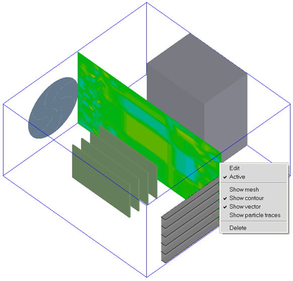
You can access a third context menu in the Graphics display window by selecting a plane cut or a point object in the Graphics display window by holding down the Shift key and the right mouse button. The context menu allows you to quickly edit, activate, or delete post processing objects in your model. Plane cut and point objects can be easily moved through the model. Hold down the Shift key, press and hold down the middle mouse button and drag the point or plane cut through the model in the graphics display.
The Graphics display context menu includes the following options:
Edit allows you to edit the properties of the post processing object.
Active allows you to toggle the item's activity.
Show mesh allows you to toggle grid display.
Show contour allows you to toggle contours display.
Show vector allows you to toggle vectors display.
Show particle traces allows you to toggle particle traces display.
Delete moves the item to the Trash node.
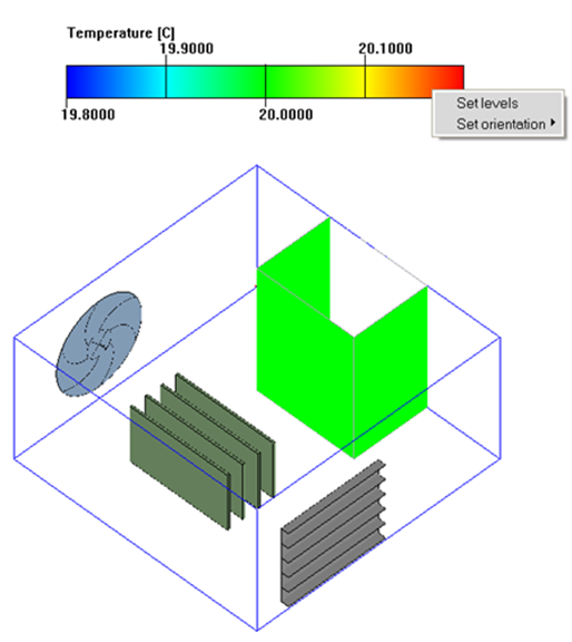
Lastly, you can access a context menu in the Graphics display window by holding down the Shift key and the right mouse button on a postprocessing legend. The context menu allows you to quickly perform common tasks on a legend in your model.
The Graphics display context menu includes the following options:
Set levels allow you to display different levels of the legend. Select Set levels in the context menu and enter the number of levels in the Set levels panel. Click Accept to update the legend.
Note: The number of levels should be at least two.
Set orientation allows you to display the legend horizontally or vertically. Select Set orientation in the context menu and click Vertical or Horizontal to update the legend.
To permanently retain changes made to the orientation and/or levels of the legend, save the project before exiting Icepak. If not, then changes made to the legend shall be retained only in the active session.