Solution Setup (Structural)
You must add at least one solution setup to each Mechanical design. The solution setup for a structural analysis includes the following settings:
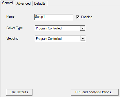
- Name: The default name is Setupx, where x is a numeric value incremented for each solution setup that you add to the design. You can customize the name of each setup as desired.
- Enabled: This option is selected by default. Deselect the option to prevent the setup from being solved when you click the Analyze All command.
- Solver Type: Specify the solver to use, or let the program choose the solver. The choices are:
- Program Controlled: This is the default setting, which is recommended for most cases. The application selects the optimal solver.
- Direct
- Iterative
- Stepping: Specify whether stepping is enabled, or let the program choose. Stepping is the process of dividing the applied loads (excitations and boundaries) into smaller increments to make solution convergence easier. In the context of structural analyses, only the loads are divided, not time increments, since time is not applicable to static analyses.
- Program Controlled: This is the default setting, which is recommended for most cases. The application determines the stepping settings.
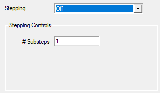
- Off: Program controlled or user-defined automatic stepping is disabled. However, you can still specify a fixed number of calculation steps. When this option is selected, the following additional setting appears in the dialog box:
- # Substeps: The number of substeps to solve.
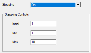
- On: User-defined stepping is enabled. When this option is selected, the following additional settings appear in the dialog box:
- Initial: The initial number of substeps to run. For the first solution increment, the applied thermal loads (boundaries and excitations) are divided according to the initial number of substeps to represent a "bite-sized" portion of the full thermal load. The default Initial substeps value is 1, in which case the full thermal load is applied initially. This number should be greater than or equal to the Min number of substeps (next bullet).
- Min: The minimum number of substeps to be solved. The default is 1.
- Max: The maximum number of substeps to solve. The default is 10. More substeps than specified by the Initial setting are solved only if convergence problems are encountered. A greater number of calculation substeps corresponds to smaller load steps, making convergence easier.
- While results are produced by the solver for each calculation substep, these intermediate results are not available for reporting in the Ansys Electronics Desktop application. Only the final solution results, based on the full values of the applied boundaries and excitations, are available for post processing.
- In the context of a structural analysis, you are not dividing the analysis into periods of time. You are only specifying load substeps, each of which has a static stress and displacement solution.
- In the absence of nonlinear materials and time-dependent or temperature-dependent excitations or boundaries, a structural analysis is likely to converge in a small number of steps without difficulty. Therefore, we recommend that you use the Program Controlled option, which allows up to ten substeps and as few as one.
Consult the Ansys Mechanical User's Guide (specifically, Configuring Analysis Settings > Analysis Settings for Most Analysis Types > Solver Controls) for more information about the available solver choices.
The Stepping options are:
There are no additional settings to specify when this Stepping option is selected.
You can think of a substep as a load division. For example, if you apply a temperature of 100 C in a Thermal Condition excitation, and you specify two substeps, the solver increments the change in temperature in two steps. In each step, the temperature increments by half of the difference between the assigned temperature and the Global (that is, stress-free) Temperature. If the stress-free temperature is 20 C, then Delta T = 80 C total and 40 C per step. Therefore, the body temperatures for steps 1 and 2, respectively, would be 60 C and 100 C. The applied thermal loads (boundaries and excitations) are divided according to the number of steps you specify and solved as intermediate steps and a final step. (See Note below).
If no convergence problems are encountered, the solver can reduce the number of substeps to something between the Initial and Minimum values, essentially increasing the size of the load step.
If you specify Min greater than Initial, the solver will reset Min to be equal to Initial. Therefore, the value you enter for Min should be less than or equal to the Initial number of substeps you define.
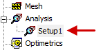
How to Set Up a Structural Solution:
- Use one of the following three methods of accessing the structural solution settings:
- On the Simulation ribbon tab, click
 Setup.
 - Right-click Analysis in the Project Manager and choose Add Solution Setup.
- Using the menu bar, click Mechanical > Analysis > Add Solution Setup.
- Optionally, change the Name and any of the other default settings (Solver Type or Stepping options) that have been previously described in this topic.
- Optionally, click HPC and Analysis Options to change any of your high performance computing configurations or options.
- Optionally, specify settings for importing a mesh from another design or project. (See Mesh Linking.)
- Click OK.
The setup appears under Analysis in the Project Manager: