Fixed Support
Fixed supports are applicable to Modal and Structural solutions. A fixed support constrains the selected entities from translating in any of the three global directions (X, Y, and Z).
You can assign Fixed Support boundaries to only the following entity types:
- Faces of solid objects (Modal or Structural solutions)
- Edges of solid objects (Structural solutions only)
- Vertices of solid objects (beta feature for Structural solutions only)
Faces or edges to which you assign a Fixed Support may be of any shape.
A Fixed Support boundary assigned to only a single straight edge or to two vertices is not sufficient to make an object statically stable (a requirement for structural solutions). Since solid elements do not support rotational degrees of freedom, an edge support cannot prevent an object from rotating about a fixed, straight edge; it can only prevent translations. Similarly, two fixed vertices cannot prevent rotation about the axis connecting the vertices. That is, a straight edge or two vertices with a fixed support assignment will act like a frictionless hinge, and the solution will fail.
Any object, or group of connected objects, with a Fixed Support boundary assigned to at least one face is statically stable. That is, there can be no rigid-body translation or rotation of the objects in any direction because a face cannot rotate if it is not free to translate.
For models that have objects or subassemblies that are not physically bonded to each other, each separate body or set of bodies must be statically stable. That is, fixed, cylindrical, or frictionless supports sufficient to prevent rigid body translations and rotations are required for each separate object or subassembly of objects.
How to Assign a Fixed Support Boundary:
- Using the Face selection mode, or optionally (for structural solutions) the Edge, Vertex, or Multi selection mode, select one or more solid object faces, edges, and/or vertices, as applicable.
- Use one of the following three methods of accessing the Fixed Support dialog box:
- Right-click in the Modeler window and choose Assign Boundary > Fixed Support from the shortcut menu.
- Right-click Boundary in the Project Manager and choose Assign > Fixed Support.
- From the menu bar, click Mechanical > Boundaries > Assign > Fixed Support.
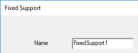
- Optionally, change the Name of the boundary. (The default name is FixedSupportx, where x is a number incremented for each fixed support you add.)
- Click OK.
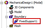
The fixed support appears under Boundary in the Project Manager: