Force
A Force excitation applies a resultant force in any desired vector direction. Force excitations can be uniform (user-specified magnitude) or non-uniform (force distribution imported from an electromagnetic simulation solution).
- For uniform forces: Specify X, Y, and Z components of force to produce the desired resultant force and direction. Global and user-defined coordinate systems are supported. The specified force components are applied to each face in the selection set. For example, if you assign a 10 newton force in the X-direction with three faces selected, the model receives a total force of 30 newton in the X-direction.
- For non-uniform forces: Set up a link to a source solution. Electromagnetic force results (specifically surface or volume force density) will be imported from the source design to the target Mechanical–Structural design.
You can assign Force excitations to the following entity types:
- Faces of solid objects
- Solid objects (only for the non-uniform option with a Maxwell 3D source design)
The faces to which you assign a Force may be of any shape or orientation, flat or curved.
The following criteria apply for EM force source designs:
- The geometry of EM force source objects in a source design must be the same as the target design objects that will receive the imported forces whether surface or volume-based. Currently, a partial model cannot be used as a source of forces for a full Structural target model.
- HFSS solutions only produce surface force density results. Therfore, when linking to an HFSS solution, the Force excitation must be assigned to faces of the target Structural model.
- Maxwell 3D solutions include both surface force density and volume force density results. Therefore, Structural Force excitations linked to Maxwell source designs can be assigned to either solid objects or faces.
Non-uniform (imported) Force excitations are not currently supported for Maxwell 3D source designs in which the solution type is Magnetic: Eddy Current. Mechanical–Structural solutions support non-uniform Forces from all other Maxwell 3D solution types.
How to Assign a Force Excitation:
- Using the Face, Object, or Multi selection mode, select one or more solid objects and/or faces, as applicable.
- Use one of the following three methods of accessing the Force dialog box:
- Right-click in the Modeler window and choose Assign Excitation > Force from the shortcut menu.
- Right-click Excitations in the Project Manager and choose Assign > Force.
- From the menu bar, click Mechanical > Excitations > Assign > Force.
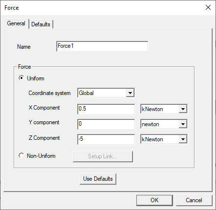
- Select one of the following Force types:
- Uniform: A constant, user-specified force will be applied at all selected faces.
- From the Coordinate System drop-down menu, choose the CS on which the force components will be based.
- Type the force component magnitudes in the X Component, Y Component, and Z Component text boxes.
- Choose the desired force units from the drop down menus to the right of each component text box. The following units are supported:
- Non-Uniform: Surface force density results will be imported from an HFSS or Maxwell 3D design, or volume force density results will be imported from a Maxwell 3D design.
- Optionally, change the Name of the excitation. (The default name is Forcex, where x is a number incremented for each force you add.)
- Click OK.
The menu will list the Global CS and any user-defined CSs that exist in the design. Global is the default selection.
fNewton, pNewton, nNewton, uNewton, mNewton, newton, kNewton, megNewton, gNewton, dyne, PoundsForce, and kp
For zero-components, the units choice doesn't matter.
Follow the procedure, How to Setup the Force Link in the Setup Link subtopic before continuing to step 4 of this procedure.
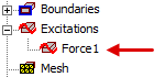
The force appears under Excitations in the Project Manager: