


Camera Model Overview
This page introduces the Camera Model to better understand its workflow and components.
Camera Use Cases in ADAS and AD
Cameras are key sensors in Advanced Driver Assistance Systems (ADAS) and Automated Driving (AD).
Generating a reliable image of the world from a specific point of view, cameras have various applications in ADAS and AD, such as:
- Lane Departure Warning System (LDWS), or Lane-keep-assist (LKA)
- Vehicles and objects recognition
- Traffic signs recognition
- Park assist system
Cameras used in ADAS and AD can be divided into two main categories:
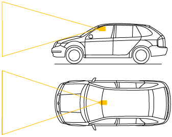
Front cameras: attached to the vehicle, usually behind the windshield, and looking forward in one direction.
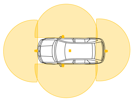
Surround view cameras: a combination of 5 wide-angle (fisheye) cameras providing a 360-degree view around the vehicle.
Camera Model Workflow
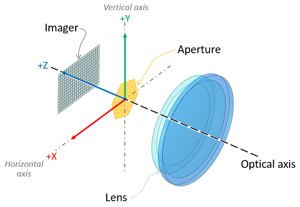
The first stage of the rendering pipeline is a perspective projection. The camera is placed at the vanishing point of the frustum. The point of reference for the position of the camera in AVxcelerate Sensor Labs (see Sensor Referential) is therefore the entrance pupil of the lens system.
The camera simulation is physics-based since the optical properties of the world input as well as the physical properties of each component of the camera are considered.
The Ansys AVxcelerate Sensors Simulator camera model workflow has three major steps as shown on the following graph.
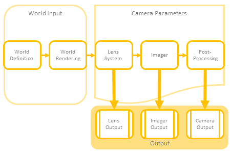
World input
World definition corresponds to:- the environment including the natural sky whose properties define the ambient lighting of the scene,
- the track and assets enhanced with physical properties (such as texture with BRDF) as well as physically accurate light sources (for which the light distribution -IES- and spectrum are defined),
- the driving scenario governing the behaviour of the assets (time and position updates).
The world rendering relies upon the virtual scene updated during the simulation.
Camera Parameters
The camera model is parametric and can simulate every component of any actual camera model:
- Lens System: the camera's geometric optics component
- Imager: the camera's light-sensitive and electronic component (sensor) which generates a raw image
- Post-processor: the camera's post-processing component
Note: The Diffraction Spike setting is considered in every camera output even though it is located in the Post Processing section in AVxcelerate Sensor Labs. The Gain setting is considered in both the Imager Output (Injection) and the Camera (Output Image) even though it is located in the Post Processing section in AVxcelerate Sensor Labs.- Camera Sensor Output DataThe camera model can either output:
- Lens output (Light): spectral irradiance map, see Lens Output (Light) Data
- Imager output (Injection): imager raw output, see Imager Output (Injection) Data
- Camera output (Image): final RGB image at the camera and rendering pipelines output, see Camera Output (Image) Data. The image format is to be defined in the Camera Simulation Parameters.