Proportional Integral (PI) Controller
Model of a Proportional Integral (PI) controller
What is a PI controller ?
A Proportional Integral controller (also known as proportional plus integral) controller combines proportional and integral control action.
A proportional controller is a controller in which the output signal is proportional to the error signal.
An integral controller is a controller in which the output signal is proportional to the integral of the error signal.
By combining both, we eliminate the major disadvantage of the integral controller which is its instability.
Consequently, the mathematical formula are


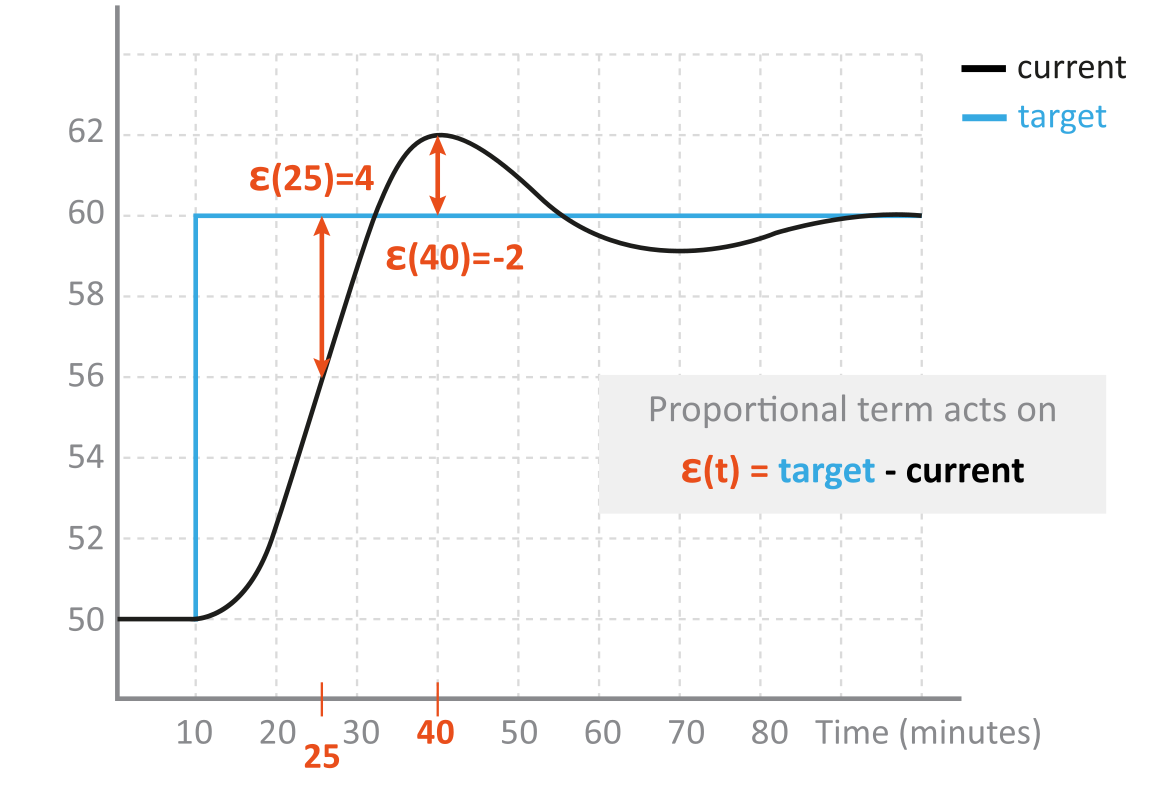
where epsilon represents the error signal and m is the control command variable. The first term is the proportional part P and the second term is the integral part I. The proportional term acts on the error, the integral term acts on the error and its duration.
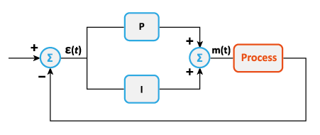
A PI controller is used to regulate a process in a feedback loop. In the image below, P represents the proportional component and I the integral component of the PI.
Integral Computation
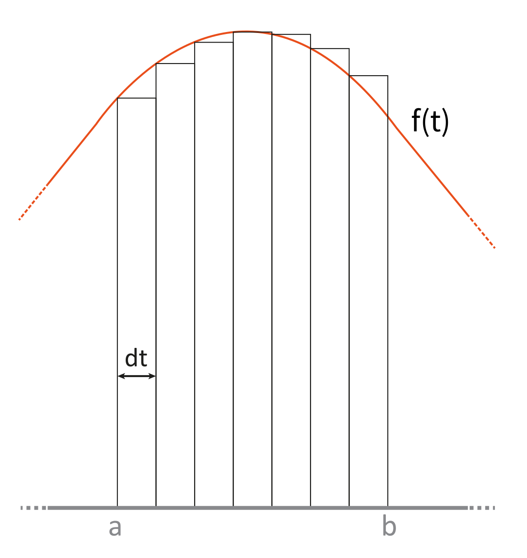
The integral is computed using the rectangle approximation method:

Modeling
The Scade One model is composed of two operators: the root operator PI, computing the regulation, and another operator Integral, computing the integral
- The PI operator
This operator implements the equations presented in What is a PI controller ?
A local variable epsilon is introduced as a probe to be able to explicitly see the value of epsilon during simulation or even execution on target.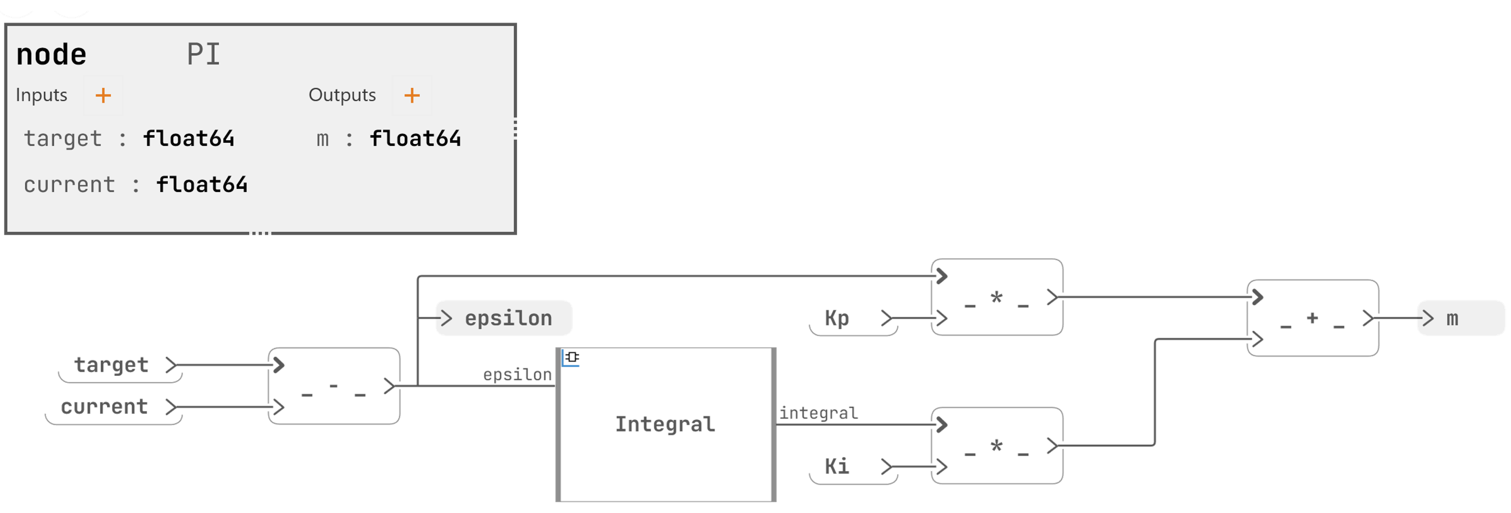
with the epsilon local variable:probe epsilon : float64 - The Integral operator
It computes the integral part of the PI controller with the method explained in section Integral Computation
node Integral (epsilon:float64) returns (integral : float64)
let integral = (0.0 pre integral) + epsilon * TCYCLE;
The initialized unit delay operator returns the value of the integral flow at the previous step, and is initialized with 0.0.
The input flow epsilon is the error (the funtion f(t) in the Integral Computation formula) and the constant TCYCLE represents the dt width of each rectangle.
- Two sensors
A sensor is a global input. In this model we use sensors to give a value to Kp and Ki.
- the proportional term:
sensor Kp : float64 - the integral term:
sensor Ki : float64
- the proportional term:
- A constant
const TCYCLE : float64 = 0.05
Model Simulation
Test
In order to perform a unitary test of the CONTROLLER::PI operator, a test harness is created, with CONTROLLER::PI as operator under test.
The TESTPACKAGE test package contains a Test harness operator PITest. A Sequence operator from the Sources library is used to give values to the current input of the PI root operator. In the Sequence operator the timeSample (duration of 1 cycle) is set to PICONTROLLER::TCYCLE seconds and the values of steps and values are set in order to make current:
- start from 30.0 to 70.0 during 2s
- then go from 70.0 to 45.0 during 1 second
- then go from 45.0 to 50.0 during 1 second
- and finally stay at 50.0 during 2s
The target value is set to
50.0during the whole simulation.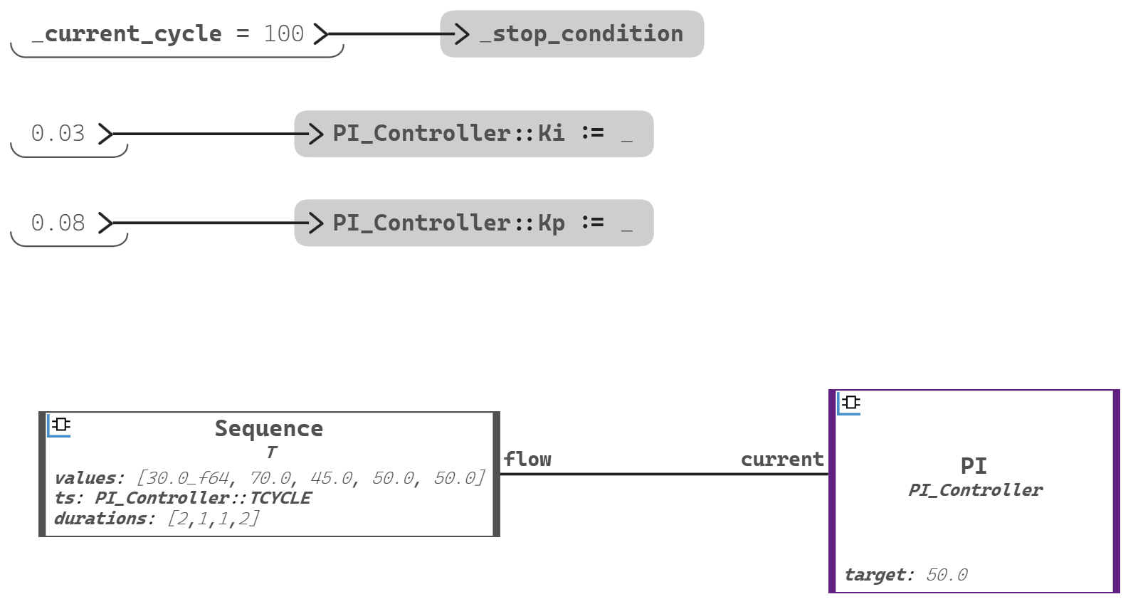
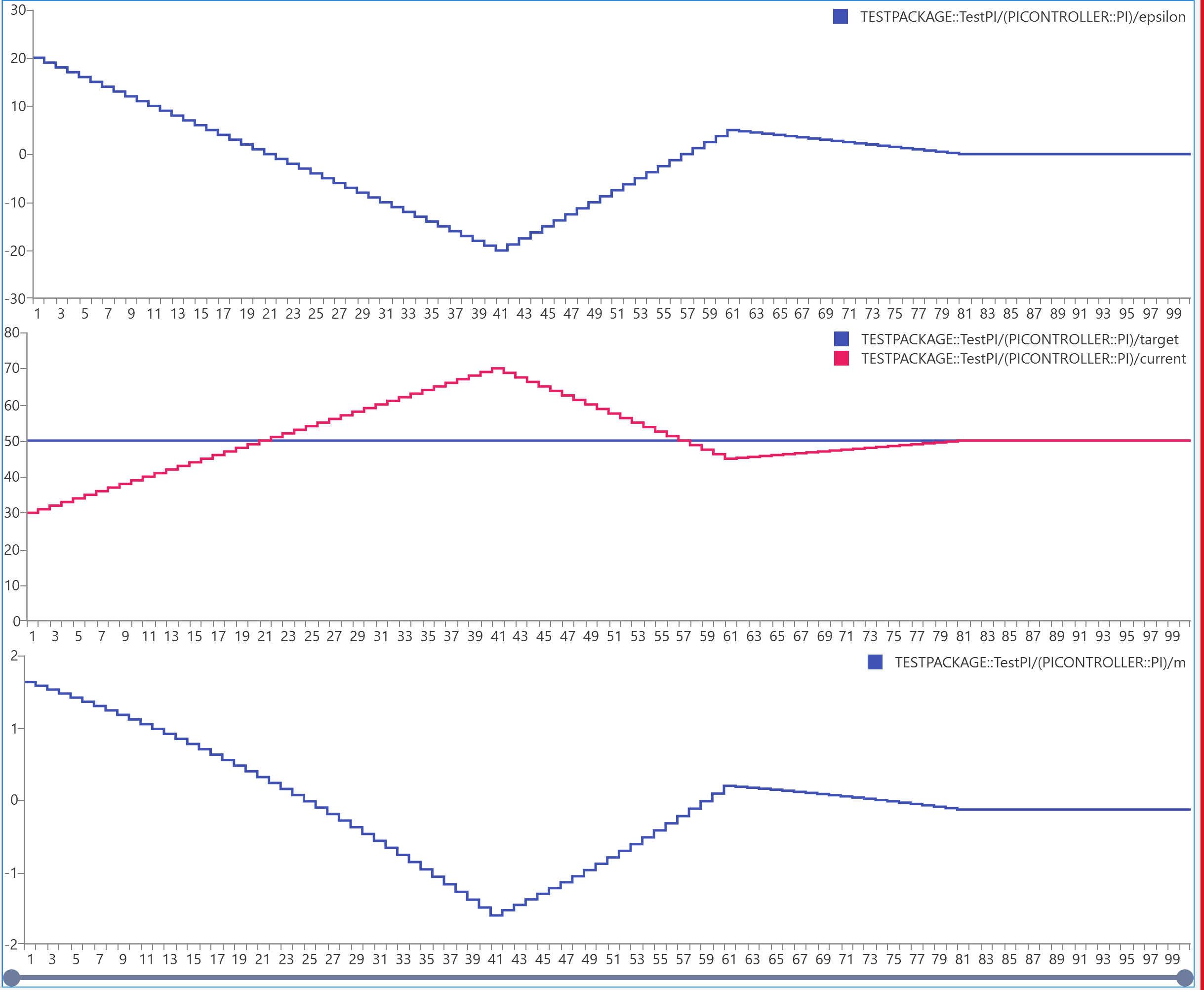
Simulation Trace
The simulation is launched with 100 cycles.
The simulation Trace shows that m evolves with the difference between target and current.
Apply an anti-windup method to the controller
The wind-up effect in a PI controller is the situation where the integral term accumulates a significant error during the rise (windup). There exists several means to correct this effect, called anti-windup. One of them consists in a feedback loop to avoid computing the integral when the controller hits specified saturation limits and enters non linear operation.
Let us apply this anti-windup method to our PI example. The control command must be saturated between 0.0 and 1.0. And if the control command was saturated at the previous step, the integral is not computed
Modeling of the anti-windup
To implement this modification on the PI model, a Limiter operator is added.
The regulation is modified to avoid calling the integral operator if the saturation was reached at the previous step.
- The Limiter operator
The Limiter operator compares the input value to the bounds, if the value is inside the bounds it is returned, else the bound is returned.
Note: In Scade One, the if-then-else operator evaluates both branches and returns the value according to the result of the condition evaluation.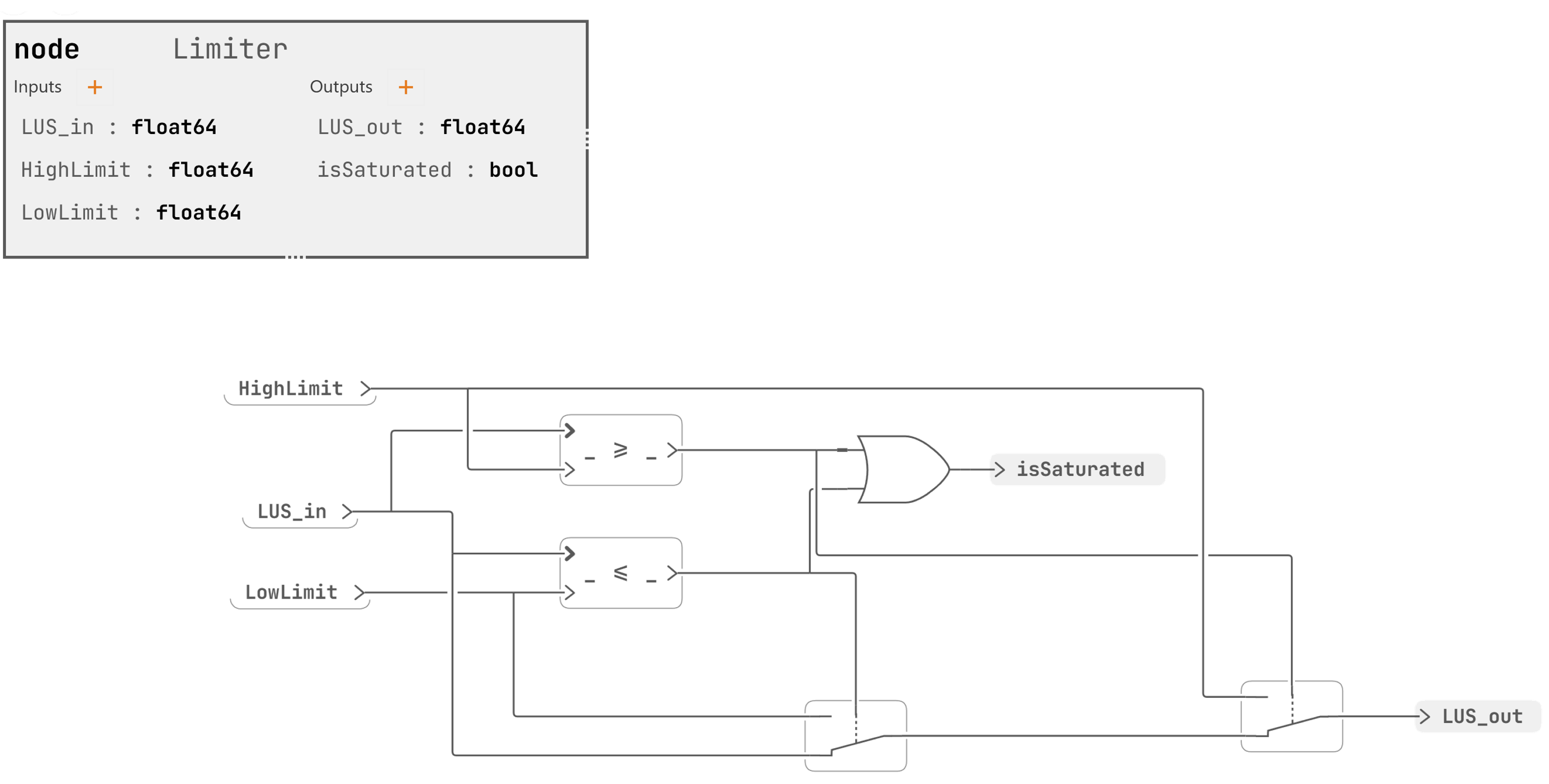
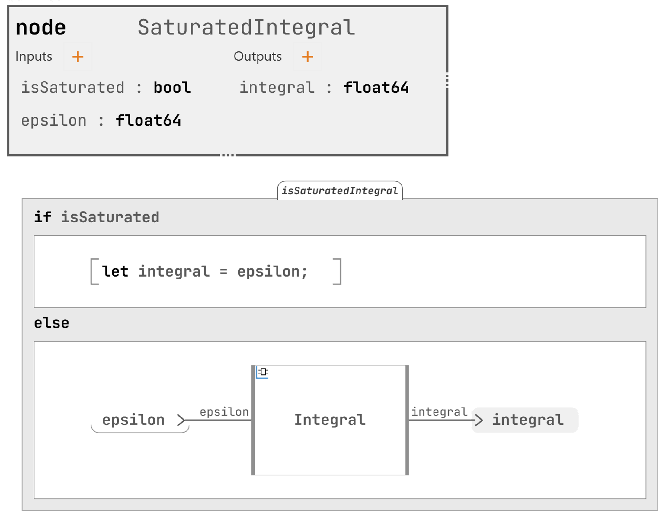
- The SaturatedIntegral operator
This operator computes the integral only if the boolean isSaturated is false.
The activate if construct computes or evaluates only the branch satisfying the condition.
-
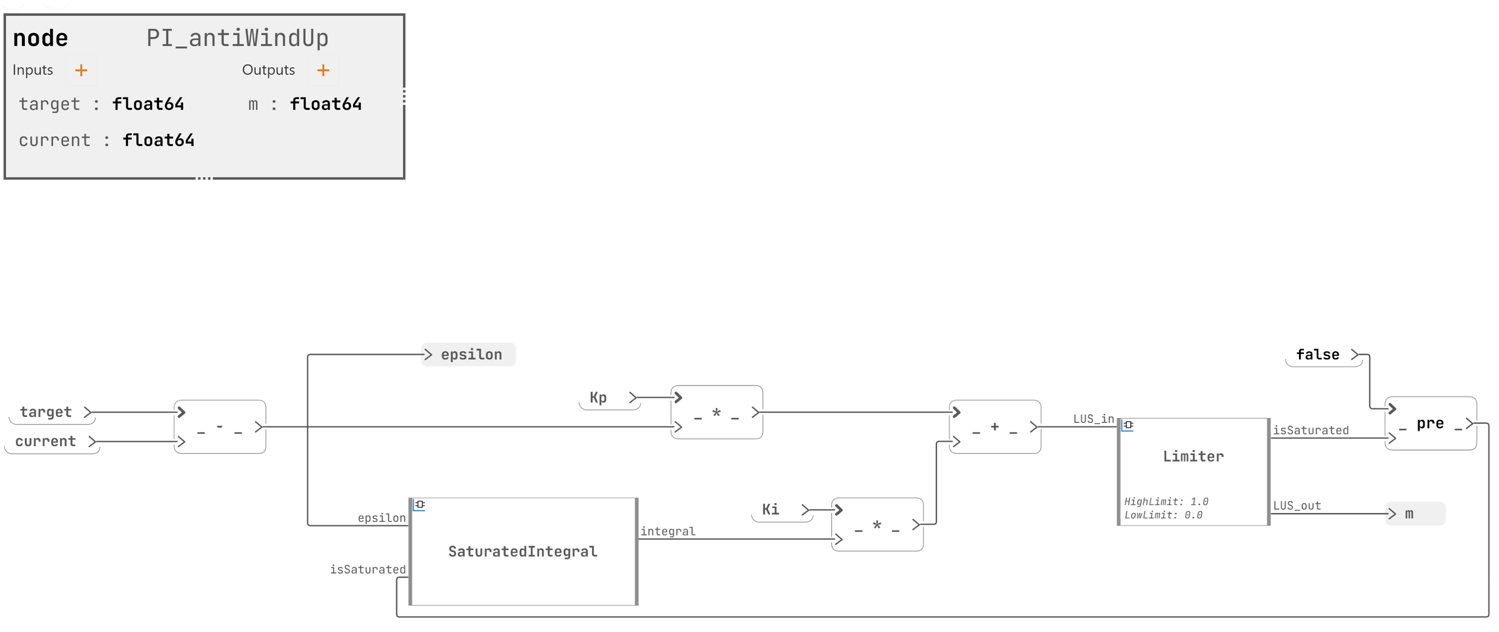
The PI_AntiWindUp operator
This operator implements the modified regulation with the anti-windup.
The initialized unit delay operator applied to the output of the Limiter returns the value of the isSaturated Boolean at the previous cycle, in order to compute or not the integral. It is initialized with false.
Note: In this diagram, the LowLimit and HighLimit inputs are defined as "textual inputs" instead of wires in instance of the Limiter operator. This is why their values are displayed in the Limiter instance, below the name.