


The Maximum member size property prevents the formation of thick features in the optimized shape. It is supported for density-based optimization, level-set based optimization, mixable density, and Shape Optimization.
Industry Motivation
This specification is motivated by several industrial manufacturing processes. Examples include:
During casting processes, a maximum member size is directly related to the cooling process of the parts where the distance to shape boundaries determines solidification times. Larger members require a more elaborate solidification system to remove the shrinkage porosity outside of the cast part and therefore increase manufacturing costs.
During additive manufacturing processes, you can avoid large members that result from the distortion created during the solidification of each layer by thermal residual stress.
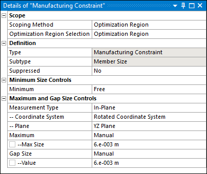
Member Size Maximum Definition
Theoretically, the computation of the maximum member size is performed in two steps:
Furthermore, the above formulation presents two critical drawbacks:
It is not derivable due to the Maximum operator and therefore is not suitable for gradient-based optimization algorithms.
As illustrated below, it is not permissive because it tracks violation regions that should be ignored [13].
However, the devised formulation is appropriately adjusted to overcome these two problems. As a result, the limit value might be violated in some limited regions of the optimized shape.
|
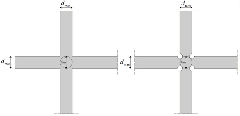
|
| Distortions close to joints of structural members to respect the maximum member size limit (dmax) in a pointwise manner; (left): dmax is not respected close to joints; (right): dmax is respected everywhere. |
For the Mixable Density and Level Set based methods, the Member Size constraint includes the Measurement Type property. It provides the following options:
Isotropic: For this setting, the formulation of member size is not directional. The constraint is satisfied when you preserve the distance in any direction. For example, for the plate illustrated below, the maximum thickness corresponds to its height.
: For this setting, the formulation of member size approximates the thickness in the selected plane. To enable this capability, when you select this option, a Coordinate System and a Plane property display. You specify a desired coordinate system that you use to define a desired plane. Using the plate illustrated below again, Plane property options specify:
YZ Plane: Maximum thickness approximates its height.
XY Plane: Maximum thickness approximates its width.
XZ Plane: Maximum thickness approximates its height.
The definition of the thickness is of particular interest when designing the ribs in cast parts, where you select the thickness plane perpendicular to the pull-out direction.
Setup and Technical Specifications
The setup requires you to specify the upper limit so that it does not exceed, denoted dmax, in terms of length. However, for the sake of accuracy in the calculation of the member size, dmax must respect a certain ratio with respect to dxAVG, as shown in the following table.
Additionally, for the Mixable Density and Level Set based methods, you can change the settings of the Measurement Type property to account for isotropic planar formulations of the thickness.
| Density Based | Mixable Density | Level Set Based | Shape Optimization | |
|---|---|---|---|---|
|
|
|
| ||
|
Exclusion Region |
Using the options, Include Exclusions or Exclude Exclusions, of the Region of Manufacturing Constraint and/or Region of Min Member Size properties of the Analysis Settings object, you can specify whether to include or exclude exclusions. |
Exclusion regions are inherently considered in the member size evaluation. In case the thickness of the exclusion region exceeds
| ||
|
Retained Threshold |
The member size is computed with respect to the 0.5 iso-contour of the density field. Modifying the Retained Threshold property changes the member size of the shape. |
NA |
NA | |
|
Measurement Type |
NA |
The property’s options, Isotropic and In-Plane, enable you to further define the thickness for your application. The In-Plane option also enables you to approximate the thickness over a specified plane as defined using the and properties. |
NA | |


Recommendations
Note the following:
The Maximum Member Size constraint tends to deliver more complex designs.
Ansys recommends that you use a fine mesh if you expect additional details in the geometry.
As with any constraint, the Maximum Member Size affects the objective performance. Specifically, if you reduce
 , the feasible domain shrinks and likely leads to a smaller
objective gain.
, the feasible domain shrinks and likely leads to a smaller
objective gain.When you set the Measurement Type property to , thin regions with large in-plane thickness may still appear. This is a limitation inherent to the approximation method.
Examples
- Pillar Structure
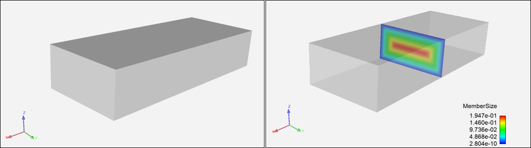
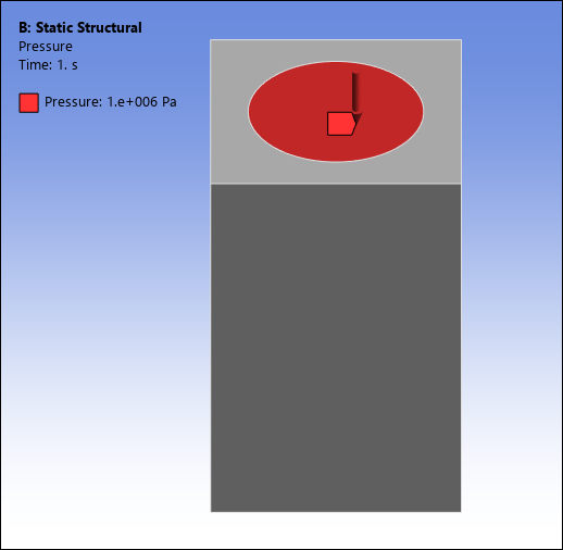
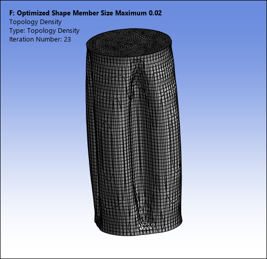
For the following example, the Optimization Type property is set to the option. This analysis uses a pillar structure clamped on the bottom with a vertical load applied to the top, as illustrated below. The optimization problem is to minimize the structural compliance under a volume fraction constraint of 0.4.
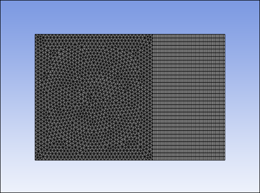
Here is the finite element mesh (144,828 elements).
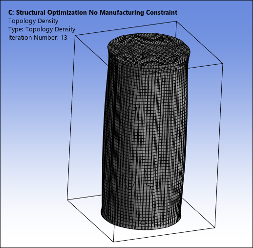
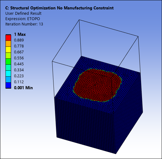
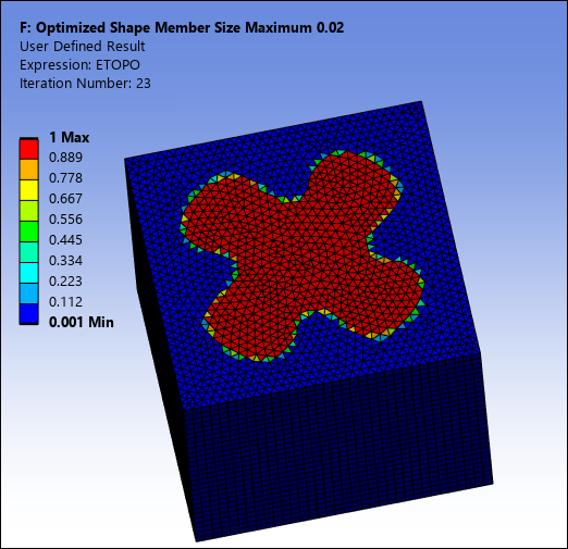
The following Topology Density result and User Defined Result, show the optimized result without considering any maximum member size constraints. As expected, the optimized shape is a cylinder. Note that the User Defined Result shown below is a cutout of the result using the Section Plane feature.
Adding an maximum member size constraint of 0.02 leads to the optimized shape shown below. One can observe the indentations that are created to satisfy the maximum member size constraint. The expected impact of the maximum member size constraint is clearly seen, reducing the maximum distance from the points inside the shape to the structural boundary.
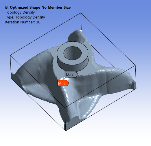
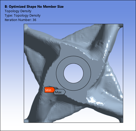
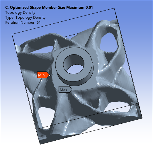
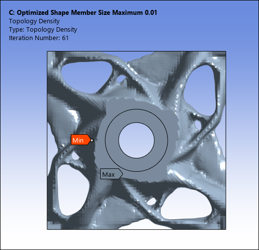
- Engine Bracket
For the following example, the Optimization Type property is set to the option. The optimization problem consists of:
Minimizing the structural compliance under a volume fraction constraint of 0.4.
A Maximum Member Size constraint with dmax = 1.0e-02.
A Pull-Out Direction constraint in the Z-direction.
A Cyclic Repetition Design Constraint with 4 sectors enforced.
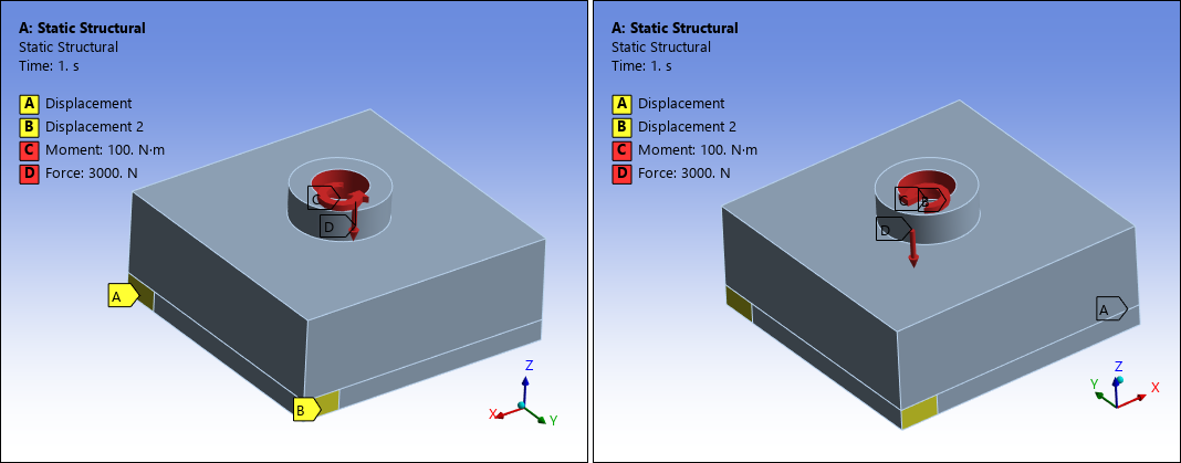
Mechanical Setup
The upstream Static Structural system is specified with two displacements, a force, and a moment, as illustrated.
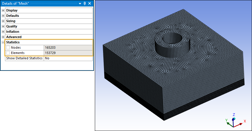
Here is the finite element mesh (153,729 elements).
The following Topology Density result shows the optimized result without considering an maximum member size constraint.
And here you can see the optimized shape and cross-sectional density for dmax of 0.01.
- Plate Reinforcement
For the following example, the Optimization Type property is set to the Topology Optimization – Level Set Based option. This analysis examines the design of a reinforcement structure above a plate structure. The optimization problem consists of:
Minimizing the structural compliance under a volume fraction constraint of 0.4.
A Maximum Member Size constraint with dmax = 6mm.
A Pull-Out Direction constraint in the Y-direction.
A double Symmetry constraint in the XY and YZ planes.
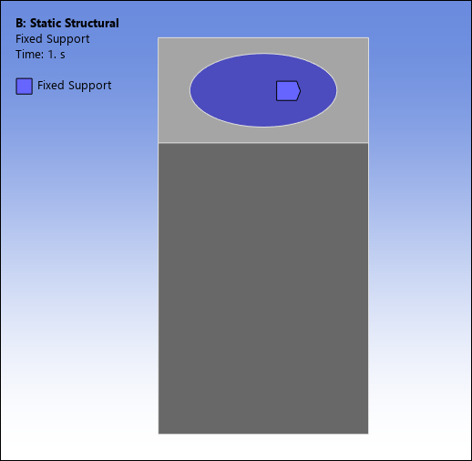
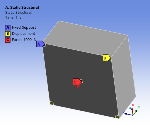
Mechanical Setup
As illustrated, the upstream Static Structural system is specified with a Fixed Support (A), one Displacement (B), and a Force (C) applied at the center of the bottom side of the body.
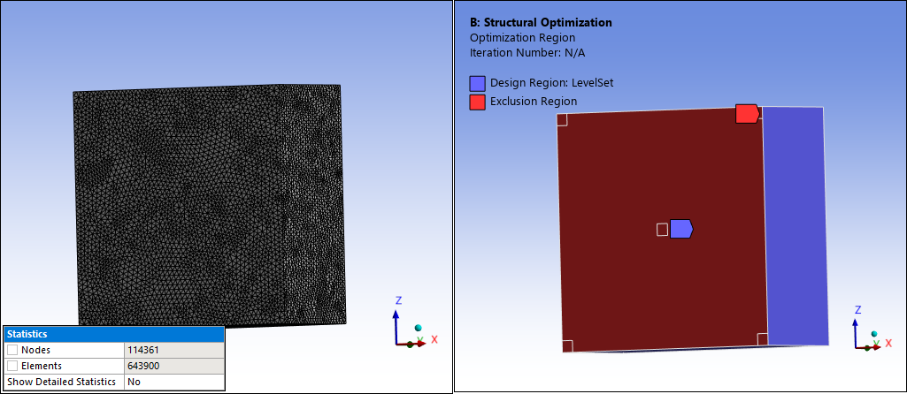
Here is the finite element mesh (643,900 elements) and the Exclusion Region.
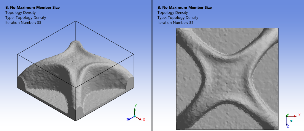
The following Topology Density result shows the optimized result without considering a maximum member size constraint.
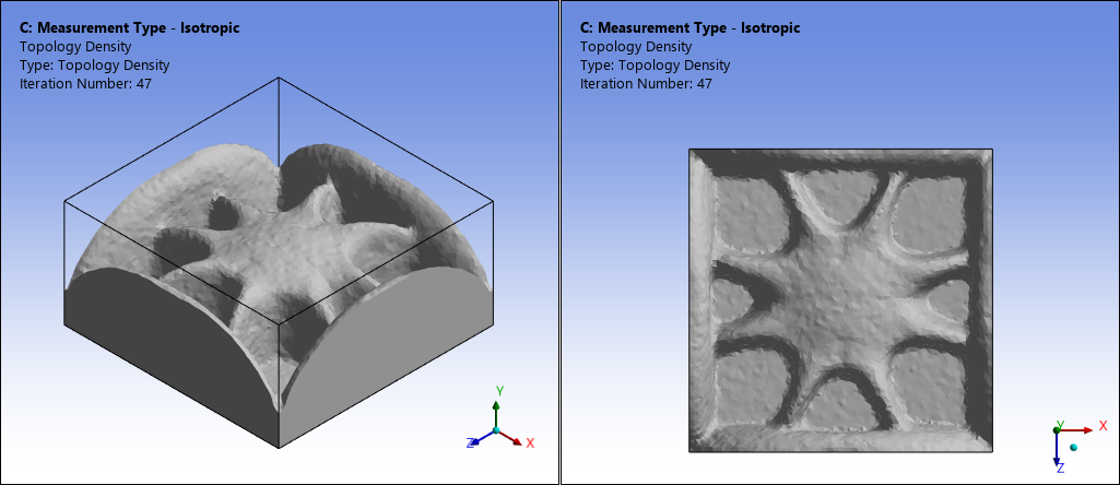
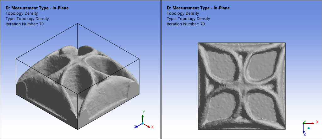
Here is a result of the optimized shape for dmax = 6mm with the Measurement Type property set to .
Here you can see the optimized shape for dmax = 6mm with the Measurement Type property set to , the Coordinate System property set to , and the Plane property set to .
For this example, you can verify how using the setting for the Measurement Type property for a Maximum Member Size constraint, together with the Pull-Out Direction constraint, can produce a rib-type structure.
References
[13] G. Allaire, F. Jouve, G. Michailidis, Thickness control in structural optimization via a level set method, Structural and Multidisciplinary Optimization, 2016.
[14] Fernandez, E., Yang, K.K., Koppen, S., Alarcon, P., Bauduin, S., Duysinx, P., Imposing minimum and maximum member size, minimum cavity size, and minimum separation distance between solid members in topology optimization. Computer Methods in Applied Mechanics and Engineering, 2020.