


To include a block in your Ansys Icepak model, click the  button in the Object
creation toolbar and then click the
button in the Object
creation toolbar and then click the  button to open the Blocks panel, shown in Figure 20.14: The Blocks Panel (Geometry Tab) and Figure 20.15: The Blocks Panel (Properties Tab).
The procedure for adding a block to your Ansys Icepak model is as follows:
Create a block. See Creating a New Object for details on creating a new object and Copying an Object for details on copying an existing object.
Change the description of the block, if required. See Description for details.
Change the graphical style of the block, if required. See Graphical Style for details.
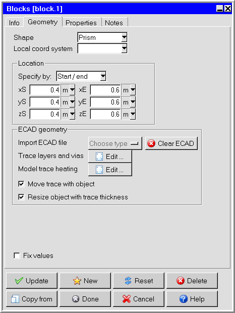
In the Geometry tab, specify the geometry, position, and size of the block. There are six different kinds of geometry available for blocks in the Shape drop-down list. The lower part of the panel will change depending on the shape. The inputs for these geometries are described in Geometry. See Resizing an Object for details on resizing an object and Repositioning an Object for details on repositioning an object.
Note: You must specify a prism geometry for a network block.
For CAD shapes, specify the center and z-axis if you want to define a rotating object with some given RPM. If you want to import ECAD into the CAD shape, you need to specify the Center, Z-axis, and X-axis to orient the ECAD to the CAD shape. In this case, the z-axis is the stacking direction and the x-axis is the local x-axis of the ECAD with respect to the CAD shape. To help define the axes, you can double-click Z-axis or X-axis in the Blocks panel and then select positions on CAD shape in the graphics window. The axes of the components are calculated from the selected points. For the x-axis, select two points that correspond to the local x-axis of the ECAD. For the z-axis, select three points to define a plane where the z-axis is the normal vector.
Note: Icepak cannnot model trace layers separately.
(solid blocks only) You can import trace files (ANF, BOOL+INFO, EDB, ODB++, and IPC2581) for solid blocks by clicking on the Import ECAD file drop-down list. See Importing Trace Files for details.
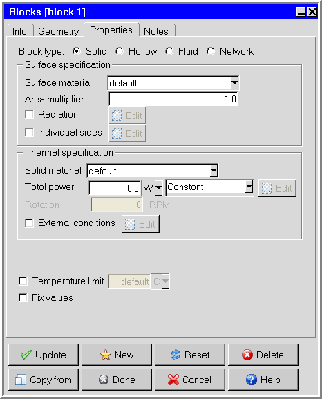
In the Properties tab, specify the type of the block by selecting Solid, Hollow, Fluid, or Network next to Block type. The lower part of the panel will change depending on your selection of Block type.
Define the Surface specification for a block of the selected type. The options for surface specification are described in User Inputs for the Block Thermal Specification.
(solid, hollow, and fluid blocks only) Define the Thermal specification (or Fluid specification) for a block of the selected type. The options for thermal (or fluid) specification are described in User Inputs for the Block Thermal Specification.
(network blocks only) Define the thermal resistance network by selecting the Network type and specifying the thermal resistances and the power dissipated by the junction. The types of network blocks and the resistances are described in User Inputs for Network Blocks.
(hollow blocks only) Specify the concentration of species at the surface of the block, if required. You can input the concentrations of the species at the surface of the block using the Species concentrations panel. To open this panel, select Species in the Blocks panel and click Edit. See Species Transport Modeling for details on modeling species transport.
(optional) Specify the Temperature limit to be used to provide a warning message in the Power and temperature limit setup panel, if the temperature of the block exceeds this specified limit. See Power and Temperature Limit Setup for more information on temperature limit setup.
Note: If you are running a transient case involving a thermal resistance network, it is recommended that you use a network object, which allows you to specify heat capacities to the network nodes. Heat capacity is an important property in transient analysis, and cannot be specified for network blocks. See Networks for more information about network objects.