


Design Failure Mode and Effects Analysis (DFMEA) is the application of the Failure Mode and Effects Analysis method specifically to product design. It is a paper-and-pencil analysis method used in engineering to document and explore ways that a product design might fail in real-world use. DFMEA documents the key functions of a design, the primary potential failure modes relative to each function and the potential causes of each failure mode. The DFMEA method allows the design team to document what they know and suspect about a product's failure modes prior to completing the design, and then use this information to design out or mitigate the causes of failure.
Ansys Sherlock supports DFMEA by providing convenient mechanisms for maintaining a DFMEA matrix using an effective hierarchical GUI, exporting all or part of the matrix to an XLS spreadsheet using one or more custom templates, and importing changes made to such spreadsheets back into Sherlock for subsequent use. Sherlock assists in the preparation of the DFMEA matrix by leveraging data from other modules, such as providing data extracted from PCB design files, data stored in the Part Database, and analysis of pin locations, to name a few examples. Finally, Sherlock provides a collection of analysis results, such as the distribution of Risk Priority Numbers (RPNs) calculated for each part in a PCB to help users understand the overall impact of their DFMEA activities.
Note: The examples shown in this document are based on the ODB++ Tutorial archive provided as part of the Sherlock Tutorial package. Follow the instructions in the ODB++ Project Creation tutorial to load that archive.
In this section, the following topics are covered:
Sherlock maintains DFMEA data as a hierarchical collection of the following types of data:
One or more Subcircuits per Circuit Card
One or more Parts per Subcircuit
One or more Failure Modes per Part
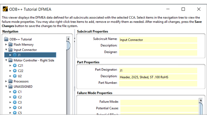
For maximum usability, DFMEA data is displayed and managed as a graphical data tree, allowing users to easily expand, collapse, browse and edit the data.
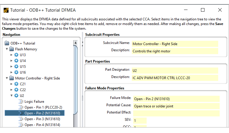
To view the DFMEA Data Tree, simply double-click the DFMEA entry located in the Circuit Card Inputs folder of the Project Tree. At that point, the DFMEA Viewer will appear as a separate window.
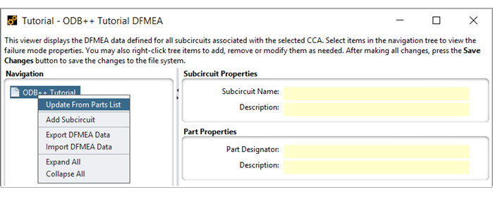
For each new circuit card, the DFMEA Viewer will initially contain no data, but you can easily add default DFMEA data entries by right-clicking the circuit card name in the Navigation panel and selecting the Update From Parts List menu option.
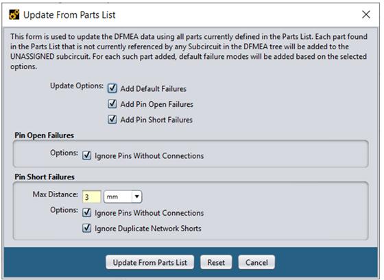
At that point, a dialog will appear (see below) allowing you to select various processing options. You may optionally create:
Default Failures based on part types
Default Open Failures for all part pins
Default Short Failures for all pairs of pins
We'll discuss these options in more detail later. For now, simply select all the update options and press the Update From Parts List button to create default DFMEA data entries for all parts in the Parts List.
Tip: The following section explains which part properties Sherlock uses in the DFMEA analysis: Tables: Required Part Properties per Analysis Type.
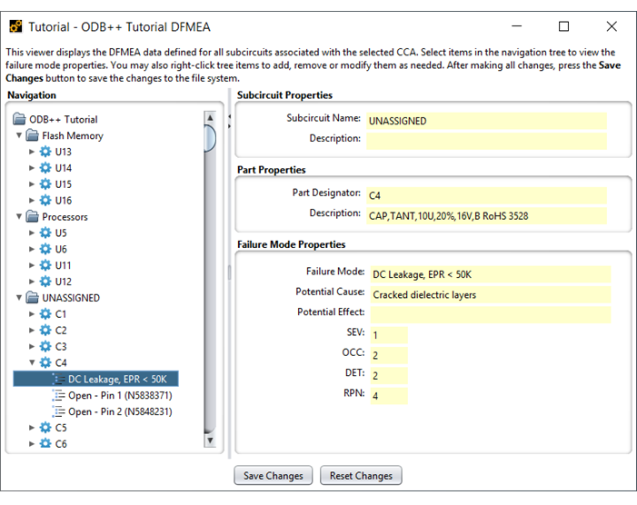
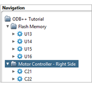
At that point, the Flash Memory, Processors and UNASSIGNED folders will be added to the Navigation panel. The Navigation panel is used to quickly find and display the data associated with any Subcircuit, Part or Failure Mode. As each entry is selected in the tree, the data corresponding to that entry, and all higher-level entries, will be displayed in the property panels located on the right-side of the main panel.
You can navigate the tree using either the mouse or the following keyboard keys:
Table 6.1: DFMEA Viewer, Keyboard Navigation
| Keyboard Key | Purpose |
| Up Arrow | Move up one row in the tree |
| Down Arrow | Move down one row in the tree |
| Right Arrow | Expand the current entry (if sub-rows exist) |
| Left Arrow | Collapse the current entry (if sub-rows exist) |
You may also double-click any row containing sub-rows to expand/collapse that entry.
By default, Sherlock places all parts found in the Parts List into one or more subcircuits designated by the Subcircuit Name(s) property value assigned to each part. In this tutorial, subcircuit names were assigned to eight of the parts (U5-U6, U11-U16) when the ODB++ archive was imported because the FUNCTIONAL_BLOCK ODB property was mapped to the Subcircuit Name(s) Sherlock property during the import process. Users can also edit the Parts List manually to assign parts to one or more subcircuits using a comma-separated list. When the Update From Parts List menu option is executed, Sherlock automatically creates the necessary subcircuit folders and assigns all parts to the appropriate subcircuit folders based on their current Subcircuit Name(s) property values. If a part is not assigned to any subcircuit, then Sherlock places it in the UNASSIGNED subcircuit folder.
Note: If you change the Subcircuit Name(s) property for one or more parts, simply re-execute the Update From Parts List menu option to move the existing DFMEA entries to the proper subcircuit folders.
You can execute the Update From Parts List menu option at any time to copy current part properties from the Parts List to the DFMEA data. Sherlock automatically copies all part property values in the Parts List to DFMEA data fields that have the same name. In the simplest case, the Description property from the Parts List is copied into the Description DFMEA field, but any part property available in the Parts List can be copied into a DFMEA field with the same name.
Note: The Customizing DFMEA Data section below describes how to create custom DFMEA data fields for Subcircuits, Parts and Failure Modes.
In addition to using the Subcircuit Name(s) property to organize parts in the DFMEA tree, you can easily assign one or more parts to a specific subcircuit using the following procedure.
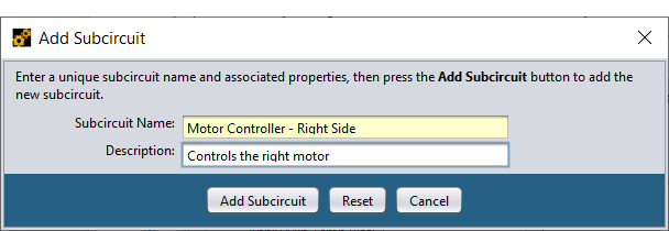
Right-click the top tree entry and select Add Subcircuit from the context menu. In the Add Subcircuit window, enter the desired Subcircuit name and optional description, then press the Add Subcircuit button to create the subcircuit definition and update the DFMEA Tree.
To assign one or more parts to the new subcircuit, select the appropriate part designators (C21 & C22 for example) in the UNASSIGNED folder, right-click any of the selected parts and select Cut Part(s) from the context menu. At that point, the parts will be copied into an internal clipboard and a confirmation dialog will appear asking if you want to remove the parts from the UNASSIGNED folder. Press Yes to remove the parts. Then, right-click the desired destination subcircuit and select Paste Part(s) from the context menu.
Note: All standard Windows-style mouse controls are supported for selecting one or more entries in the Navigation tree. Use the SHIFT key to include all entries up to a selected entry and the CONTROL key to toggle individual entries. Once the set of data entries has been selected, right-click any selected entry to remove, cut, or copy the selected entries.
Note: After one or more DFMEA data modifications are made you need to press the Save Changes button to save all changes. If you decide not to save the changes, you may press the Reset Changes to reset the DFMEA Viewer to show the previously saved data.
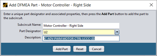
In some cases, you may want to add DFMEA data for parts or groups of parts that are not listed in the Parts List. Parts can be added simply by right-clicking any existing subcircuit and selecting the Add Part menu item in the context menu.
For example, right-click the new Motor Controller - Right Side subcircuit in the DFMEA tree and select Add Part from the context menu. Enter the desired Part Designator (or select it from the pull-down choice list). After you enter or select the Part Designator, Sherlock will automatically fill in the Description field using the value found in the current Parts List, if any.
Note: The same part may be assigned to any number of subcircuit folders to allow you to organize DFMEA data as needed to suit your requirements. In the previous example, we added U2 to the Motor Controller - Right Side subcircuit, but there is also a default entry in the UNASSIGNED folder.
You are not limited to a single part reference in the Part Designator field. Although that is normally the case, you may also enter a list and/or range of part designators, such as R1-R5, R7, R13.
Now that we've added a part, we can use Sherlock to help create the failure modes associated with each of those parts, similar to how the Update From Parts List menu option worked. To that end, right-click the U2 entry just created and select Add Default Failures from the context menu. At that point, Sherlock will automatically add one or more Failure Mode entries to the U2 part folder, as shown here:
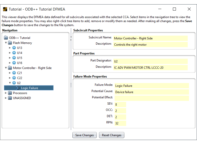
By examining the new entry, we can see that Sherlock has automatically filled in many of the properties for each Failure Mode added. Such default entries significantly reduce the time needed to manually enter DFMEA data. We'll shortly discuss how to customize the default failure modes to suit your specific project needs.
In addition to default part failures, Sherlock can generate default Pin Open Failures for all pins associated with a given part based on the Net List data imported by Sherlock.
Note: Net List data is automatically imported by Sherlock when processing ODB++, IPC-2581, and Eagle CAD files with no additional user input required. For other projects, a standard IPC-D-356 file can be used to import the necessary data. See the Net List section for more details.
To generate default Pin Open Failures, right-click the U2 part entry in the DFMEA Tree and select the Add Pin Open Failures option from the context menu.
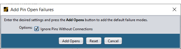
Typically, pins that are not connected to any network are ignored, but you may include those pins if necessary. After the Add Opens button is pressed, an Open - Pin XX failure entry will appear under the selected part entry in the DFMEA Tree.
Perhaps the most tedious DFMEA data entry chore is that of accounting for shorts between adjacent pins for each part being analyzed. Sherlock can significantly speed-up such a task by automatically determining which pins are adjacent to others, by generating default failure entries for all such pin pairs and by eliminating duplicate short failure modes.
To add default Pin Short Failures, right-click the U2 part entry in the DFMEA Tree and select the Add Pin Short Failures option from the context menu.
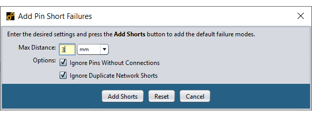
Much like Pin Open Failures, you may choose to ignore pins without connections. You may also choose to ignore duplicate network shorts. Sherlock considers two shorts to be duplicates if a pin shorts to two different pins, but both pins are connected to the same network. The Max Distance property can be used to specify the maximum distance used to determine pin adjacency.
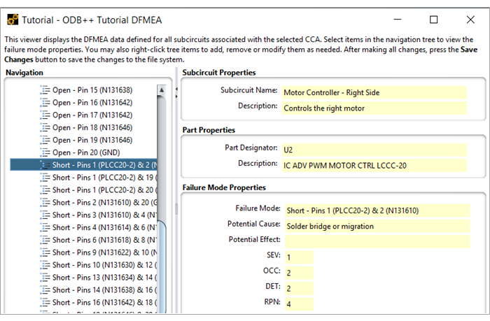
After the Add Shorts button is pressed, a Short - Pins XX & YY entry will appear under the selected part in the DFMEA Tree for each pair of adjacent pins found by, as shown below.
By default, displays the pin number and network associated with each pair of adjacent pins.
Note: The Customizing DFMEA Data section below describes how to customize the data values used when generating default Part Failures, Pin Open Failures, and Pin Short Failures.
If the default failure modes describe above don't cover all the possibilities for a given part, you can create a Failure Mode Item manually by right-clicking the part and selecting Add Failure Mode to display the dialog shown here.
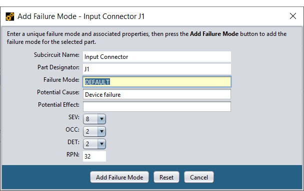
One or more of the fields in the dialog may be initially filled in by Sherlock based on the current default failure mode definition. In either case, modify the properties as necessary and press Add Failure Mode to create the failure mode item for the selected part.
For part J1, we have also created a new subcircuit called Input Connector, and used the same process described earlier in the Manually Organizing DFMEA Data section.
DFMEA data can be edited at any time simply by right-clicking the desired item in the tree and selecting either Edit Subcircuit, Edit Part or Edit Failure Mode from the context menu. At that point, the dialogs shown above will be displayed, allowing you to modify any or all the properties associated with that entry.
DFMEA data removal is accomplished by right-clicking the desired item in the tree and selecting either Remove Subcircuit, Remove Part or Remove Failure Mode from the context menu. Sub-entries are automatically removed from the tree along with the selected entry.
Note: After making one or more changes to the DFMEA Data Tree, press the Save Changes button at the bottom of the DFMEA panel to save the changes to the file system or the Reset Changes button to undo all changes made since the last time changes were saved.
DFMEA data is used in different ways by different organizations. Although there are a few standard properties across all organizations, it is often necessary and/or desirable to manage a set of properties that are organization specific. Sherlock supports such flexibility by using two user-customizable definition files to determine the properties to be displayed and edited, as well as the values to be entered automatically for default failure modes.
Sherlock uses the dfmeaProperties.csv file located in the DFMEA sub-folder in the Sherlock User Directory (C:\Users\USERID\AppData\Roaming\Sherlock\DFMEA) to determine the properties to be displayed and edited for a given DFMEA data entry. That file is created automatically as needed by Sherlock from a standard template containing a standard list of Subcircuit, Part and Failure Mode properties. You may modify that file as needed to define whatever properties are suitable for your organization. The next time that Sherlock is started, it will make use of those properties in all DFMEA displays and dialogs. If you are unsure of the location of your Sherlock User Directory, select Settings > General Settings and navigate to the Advanced subtab. The Default Project Directory shows the location of the Sherlock User Directory.
The dfmeaProperties.csv file is not complicated or hard to understand. For example, here is the standard property definition file provided by Sherlock.
Table 6.2: dfmeaProperties.csv
| Level | Property |
| Subcircuit | Description |
| Part | Description |
| FM | Potential Cause |
| FM | Potential Effect |
The first row contains the column names used by Sherlock to parse the file and should always contain exactly the column names shown here. All subsequent rows define the property names to be used for each level of data (for example, Subcircuit, Part or Failure). In this example, we've defined Description fields for both Subcircuit and Part data items. We've also defined two other properties (Potential Cause and Potential Effect) for Failure Mode items.
Aside from the properties defined in the property definition file, Sherlock hard-codes the following properties so that they always exist:
Table 6.3: Hardcoded DFMEA Properties
| Level | Property | Description |
| Subcircuit | name | Unique subcircuit name |
| Part | refDes | Unique part reference designator |
| FM | mode | Unique failure mode |
| FM | SEV | Severity Rating (1-10) |
| FM | OCC | Occurrence Rating (1-10) |
| FM | DET | Detection Rating (1-10) |
You should NOT create duplicate definitions for these properties in the property definition file.
Let's create some additional properties to see how they can be used. Using your favorite spreadsheet application, edit the dfmeaProperties.csv file and add the following rows to the bottom of the spreadsheet:
Save the file changes and the restart Sherlock. By examining the DFMEA Tree, you'll see that the Designer property has been added to the Subcircuit Properties panel and that the Part Number property has been added to the Part Properties panel.
In addition to being added to the read-only panels, those fields have been added to the Subcircuit and Part Edit dialogs so you can manually assign values to all of the new properties whenever you want.
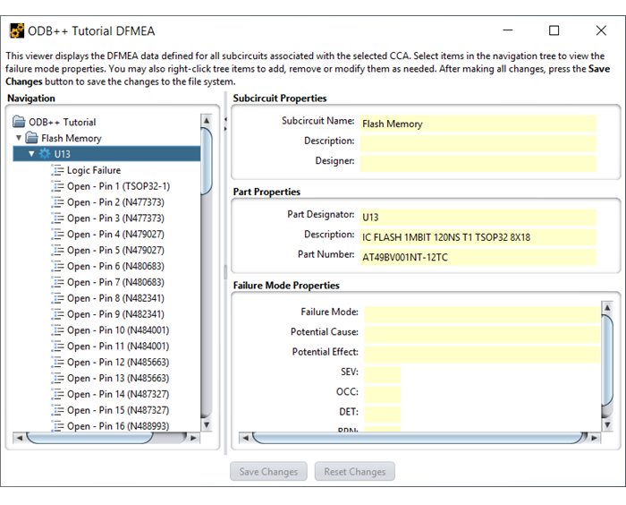
It is important to note that the Part Number DFMEA property we just added is named the same as the Part Number property in the Parts List. As such, whenever the Update From Parts List menu option is executed, Sherlock will automatically copy the Part Number value from the Parts List into the Part Number field of each corresponding DFMEA part entry. To see how this works, simply execute Update From Parts List and select U13 in the DFMEA Tree (under the Flash Memory subcircuit) to see that the part number has been copied from the Parts List.
Much like DFMEA properties, Sherlock determines the appropriate default failure modes for a given part by examining the contents of the dfmeaFailures.csv file located in the DFMEA sub-folder in the Sherlock User Directory. That file is created automatically by Sherlock from a standard template, but you are free to modify that file at any time to customize the default failure modes to be used for your projects.
The dfmeaFailure.csv file is formatted as a standard Comma Separated Value (CSV) file and can be viewed/edited using any spreadsheet application. Below is an excerpt from the default file provided by Sherlock (formatted for readability).
The first row contains the column names used by Sherlock to parse the file. The first two columns are always required to define a default failure mode. If any of the standard numeric columns (SEV, OCC, DET) are not defined, then a default value will be used. Finally, zero or more additional columns may be defined to specify default values for any of the customized Failure Mode properties defined in the Property Definition File (see previous section). In this case, we've defined only the Potential Cause for each Failure Mode, which is one of the two default properties defined by Sherlock.
Table 6.5: dfmeaFailure.csv
| partType | failureMode | SEV | OCC | DET | Potential Cause |
| DEFAULT | DEFAULT | 8 | 2 | 2 | Device failure |
| DEFAULT OPEN | Open – Pin <pinName> (<netName>) | 1 | 2 | 2 | Open trace or solder joint |
| DEFAULT SHORT | Short – Pins <pinName1> (<netName>) | 1 | 2 | 2 | Solder bridge or migration |
| Capacitor | DC Leakage, EPR < 50K | 1 | 2 | 2 | Cracked dielectric layers |
| Diode | DC Leakage | 1 | 2 | 2 | Damage to PN Junction |
| Resistor | High Resistance | 1 | 2 | 2 | Crack propagation through part |
| Resistor | Shorted | 1 | 2 | 2 | Device failure |
| Resistor Network | DC Leakage | 1 | 2 | 2 | Device failure |
| IC | Logic Failure | 8 | 2 | 2 | Device failure |
Sherlock uses the partType listed in each row to determine which default failure modes to use for a given part. Specifically, if the part type matches the partType value (case-insensitive) in the spreadsheet, then that row will be used to create a default failure mode. In the example above, one default failure mode is defined for Capacitor parts and two (2) other default failure modes are defined for Resistor parts.
Part types DEFAULT, DEFAULT OPEN and DEFAULT SHORT are used to generate default Part Failures, default Pin Open Failures and default Pin Short Failures, respectively, as we now discuss.
The DEFAULT row in the dfmeaFailures.csv file defines the property values to be used by Sherlock when generating default part failures as a result of the user selecting the Add Failure Mode menu option. In such cases, the mode property will be specified by the user before the failure mode is added.
The DEFAULT OPEN row in the dfmeaFailures.csv file defines the property values to be used by Sherlock when generating default Pin Open Failures as a result of the user selecting either the Update From Parts List or Add Pin Open Failures menu options. Since multiple pin open failures can be generated for a given part, the failureMode value specified in the CSV file is used by Sherlock as a template to generate the specific failure mode label. The template value may contain any of the following variables, which will be replaced by the indicated value:
Table 6.6: Template Variables (Default Opens)
| Template Variable | Replacement Value |
| <partName> | ID associated with the selected part |
| <pinName> | ID associated with the current pin |
| <netName> | ID associated with the connected network |
For example, the default template:
| Open - Pin <pinName> (<netName>) |
will generate the following mode:
| Open - Pin 20 (GND) |
for pin 20 connected to network GND.
Note: Net Lists may use arbitrary strings for pin names, so don't be surprised if you don't see pin numbers in some cases. Similarly, networks can be labeled using arbitrary, sometimes meaningless, strings, depending on how the circuit engineer manages them.
The DEFAULT SHORT row in the dfmeaFailures.csv file defines the property values to be used by Sherlock when generating default Pin Short Failures as a result of the user selecting either the Update From Parts List or Add Pin Short Failures menu options. Since multiple pin short failures can be generated for a given part, the failureMode value specified in the CSV file is used by Sherlock as a template to generate the specific failure mode label. The template value may contain any of the following variables, which will be replaced by the indicated value:
Table 6.7: Template Variables (Default Shorts)
| Template Variable | Replacement Value |
| <partName> | ID associated with the selected part |
| <pinName1> | ID associated with the first pin |
| <netName1> | ID associated with the first connection |
| <pinName2> | ID associated with the second pin |
| <netName2> | ID associated with the second connection |
For example, the default template:
| Short - Pins <pinName1> (<netName1>) & <pinName2> (<netName2>) |
will generate the following mode
| Short - Pins 19 (N131646) & 20 (GND) |
for adjacent pins 19 and 20 connected to networks N131646 and GND, respectively.
Sherlock provides a flexible, user-customizable mechanism for exporting all or part of the DFMEA data to one or more spreadsheet files using a collection of spreadsheet templates. Template files are formatted as standard XLS spreadsheet files, allowing you use the full range of spreadsheet formatting capabilities to specify the output file layout. In addition, Sherlock defines a set of template variables that can be referenced in a template file to include individual DFMEA data values, as well as lists of DFMEA data entries. Using such capabilities, you can easily create an output spreadsheet containing only the data associated with a selected failure more for a selected part, a summary of DFMEA data, or the entire DFMEA Data Tree, to name a few examples.
Sherlock provides the following collection of standard template files as part of the installation package:
00-Backup-Template.xls: Generates a no-frills spreadsheet containing the entire DFMEA Data Tree for a selected CCA, including the data properties defined by Sherlock by default.
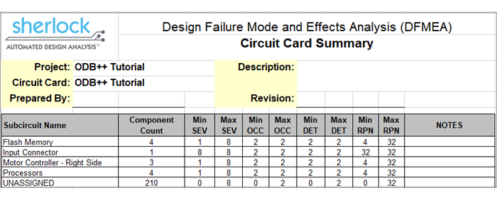
01-CCA-Summary-Template.xls: Generates a summary spreadsheet containing a list of all subcircuits defined for a selected CCA that shows the number of components contained in each subcircuit and the range of SEV, OCC, DET and RPN values for each subcircuit.
02-CCA-Details-Template.xls: Generates a detailed spreadsheet containing the entire DFMEA Data Tree, with full details for all subcircuits, components and failure modes for a selected CCA. This template also provides summary information (for example, min/max numeric values) for all subcircuits and components.
03-Subcircuit-Summary-Template.xls: Generates a summary spreadsheet containing the min/max numeric values of all subcircuit and component data for a selected CCA.
04-Subcircuit-Details-Template.xls: Generates a detailed spreadsheet containing all component and failure mode data for a selected subcircuit.
05-Part-Template.xls: Generates a detailed spreadsheet containing all failure mode data for a selected subcircuit component.
06-Failure-Mode-Template.xls: Generates a detailed spreadsheet containing the failure mode data for a selected subcircuit component failure mode.
All the template files listed above are created automatically by Sherlock in the DFMEA folder located in the Sherlock User Directory. You are free to use the templates as-is or modify them to suit your specific needs, as we now discuss.
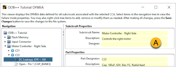
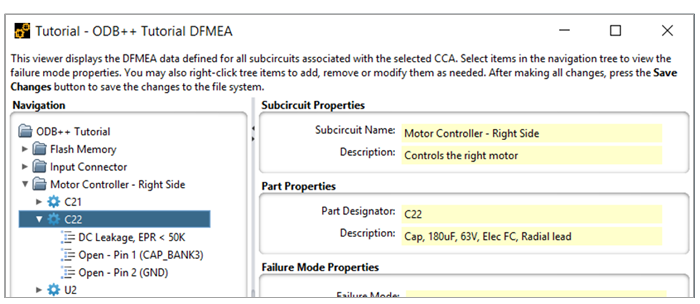
Exporting DFMEA data involves simply selecting the desired DFMEA data item to be exported and an appropriate template file. To see how this works, select the DC Leakage, EPR < 50K failure mode for the C22 component in the Input Connector subcircuit as shown below (A).
Then, right-click that entry and select Export DFMEA Data from the context menu. At that point, a dialog will appear (B) allowing you to select an appropriate template file, specify an output file and choose various processing options.
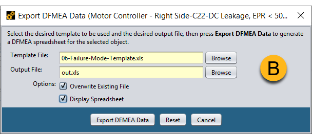
Use the first Browse button to select the failure mode template provided by Sherlock from the DFMEA folder located in the Sherlock User Directory.
Then use the second Browse button to specify the name and location of an output file to be generated.
If the Overwrite Existing File option is selected, then any existing output file with the same name will be overwritten without prompting you.
If the Display Spreadsheet option is selected, then the application currently associated with XLS files on your system (for example, Excel, Open Office) will be used to display the output file after it has been generated.
Press the Export DFMEA Data button to generate the spreadsheet using the selected template file.
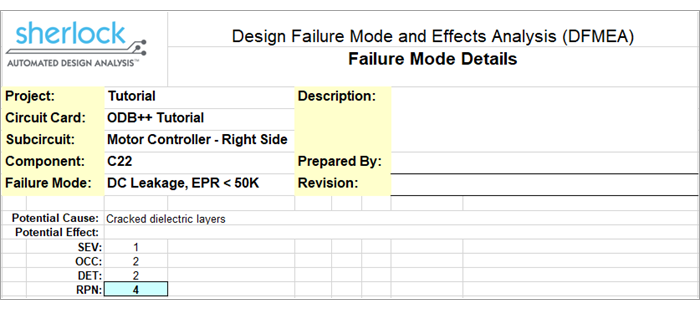
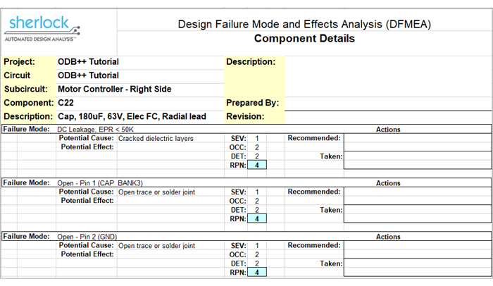
This simple spreadsheet includes a header section showing various Project, CCA, Subcircuit and Component properties, as well as the selected Failure Mode. Below the header, the spreadsheet contains a single row for each failure mode property.
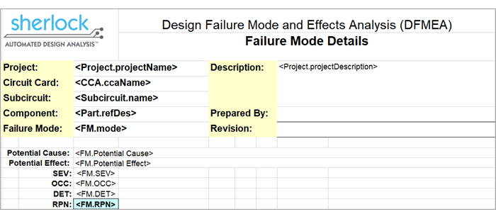
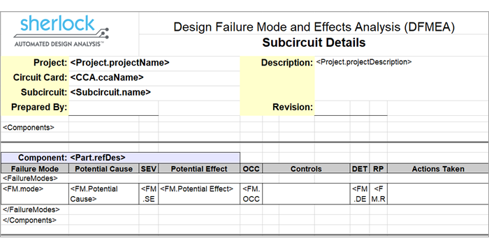
If we look at the 06-Failure-Mode-Template.xls that was used in the previous example:
And compare it to the output file:
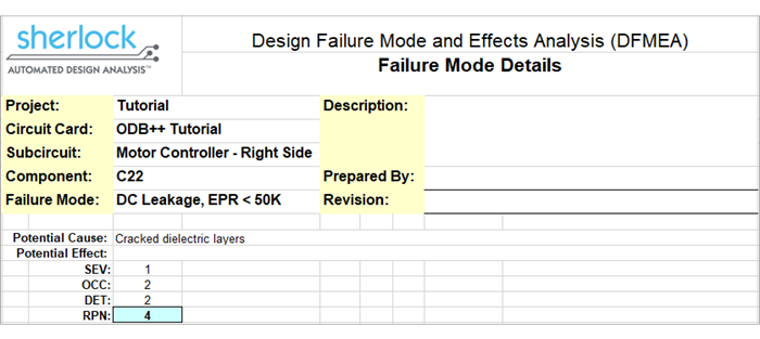
We see immediately that the output file mimics the look-and-feel of the template file, including all the same formatting and style settings. The only differences between the template and output files are those cells containing template variables. Specifically, all template variables found in the template file are replaced by their corresponding property values in the output file. For example, the <Project.projectName> template variable is replaced by “Tutorial” in the output file. This simple mechanism allows you to customize templates as needed to satisfy a range of needs.
Sherlock supports the following internally defined template variables:
Table 6.8: Internally Defined Template Variables
| Variable Name | Description |
| Project.projectName | Name of selected project |
| Project.projectDescription | Description defined in the Project Properties |
| CCA.ccaName | Circuit card name |
| CCA.ccaDescription | Description defined in the Circuit Card Properties |
| Subcircuit.name | Subcircuit Name |
| Subcircuit.componentCount | Number of components contained by the subcircuit |
| Subcircuit.minSEV | Minimum SEV value for all subcircuit components |
| Subcircuit.maxSEV | Maximum SEV value for all subcircuit components |
| Subcircuit.minOCC | Minimum OCC value for all subcircuit components |
| Subcircuit.maxOCC | Maximum OCC value for all subcircuit components |
| Subcircuit.minDET | Minimum DET value for all subcircuit components |
| Subcircuit.maxDET | Maximum DET value for all subcircuit components |
| Subcircuit.minRPN | Minimum RPN value for all subcircuit components |
| Subcircuit.maxRPN | Maximum RPN value for all subcircuit components |
| Part.refDes | Component reference designator |
| Part.minSEV | Minimum SEV value for all failure modes |
| Part.maxSEV | Maximum SEV value for all failure modes |
| Part.minOCC | Minimum OCC value for all failure modes |
| Part.maxOCC | Maximum OCC value for all failure modes |
| Part.minDET | Minimum DET value for all failure modes |
| Part.maxDET | Maximum DET value for all failure modes |
| Part.minRPN | Minimum RPN value for all failure modes |
| Part.maxRPN | Maximum RPN value for all failure modes |
| FM.mode | Failure Mode |
| FM.SEV | SEV value |
| FM.OCC | OCC value |
| FM.DET | DET value |
| FM.RPN | RPN value |
In addition to these internally defined variables, Sherlock will also recognize variables based on each of the custom Subcircuit, Part or Failure Modes properties defined in the dfmeaProperties.csv definition file (as discussed in previous sections).
For example, since Sherlock defines the DFMEA data properties in the default dfmeaProperties.csv file (see columns A and B in table below), the template variables (column C) will also be supported:
Table 6.9: DFMEA Data Properties
| A Level | B Property | C Template Variables |
|
Subcircuit |
Description |
<Subcircuit.Description> |
|
Part |
Description |
<Part.Description> |
|
FM |
Potential Cause |
<FM. Potential Cause> |
|
FM |
Potential Effect |
<FM. Potential Effect> |
Note: Custom property names are always case-sensitive and all blanks must be specified in the template variable referenced exactly as they are specified in the property definition file.
Template variables may be referenced by themselves or as part of an arbitrary string containing one or more template variables. For example, the following string expression in the template file:
| Cause (<FM. Potential Cause>) & Effect (<FM. Potential Effect>) |
would produce the following cell value in the output file:
| Cause (Cracked dielectric layers) & Effect () |
using the same inputs as the previous example (substitutions are shown in bold).
Note: If Sherlock cannot determine a value for a given template variable, then the template variable itself will be used as the cell value in the output spreadsheet.
In addition to template variables, templates may reference template lists to include a list of data entries in the output file. Specifically, the following template lists are supported by Sherlock:
Table 6.10: Template Lists
| Template List | Alias | Description |
| <Subcircuits> | None | Lists all subcircuits associated with the current circuit card |
| <Components> | <Parts> | Lists all parts associated with the current subcircuit |
| <FailureModes> | <Failures> | Lists all failure modes associated with the current part |
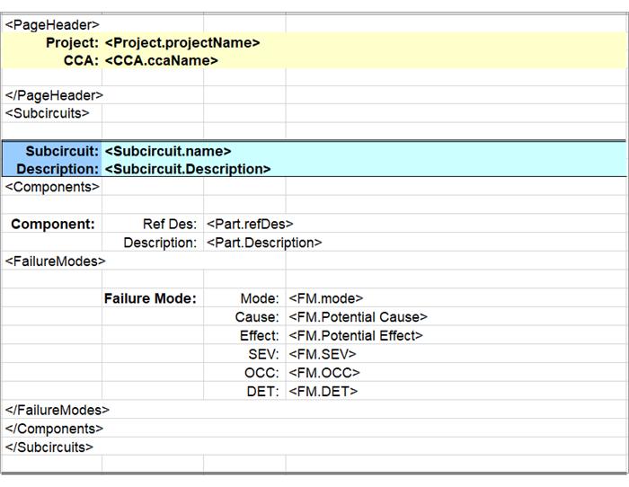
Such list references can be used individually or in a nested manner to generate a wide variety of output spreadsheets. For example, let's examine how the 05-Part-Template.xls template file uses both template variables and template lists to show all failure modes associated with a selected part.
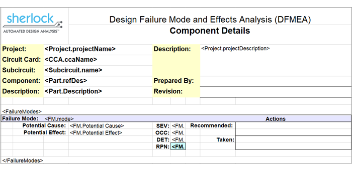
As in the previous example, the header section contains references to individual template variables to display various project, circuit card, subcircuit and component property values. Then, the <FailureModes> list is referenced, indicating that the output file should contain data for each failure mode associated with the current part. All of the lines defined between the opening <FailureModes> tag and the closing </FailureModes> tag are part of the template used to display each Failure Mode.
Note: Template list opening and closing tags must always be paired properly in the template file. If Sherlock cannot find the closing tag for a given opening tag it will generate an error message.
To see how Template Lists are used, select the U2 part (or any failure mode associated with the U2 part) in the Motor Controller - Right Side subcircuit as shown here.
Then, right-click that entry and select Export DFMEA Data from the context menu. When prompted for the template file, select the 05-Part-Template.xls file and press Export DFMEA Data to generate the following output file:
As in the previous example, the header section is reproduced exactly as shown in the template file, with property values substituted for each template variable. The remainder of the file was generated by repeatedly using the <FailureModes> template list defined in the template file. For each failure mode associated with the selected part, the template list is used to display the failure mode properties.
Template lists can be nested in a natural order to export any part of the DFMEA data tree. Specifically, the <Subcircuits> template list may include references to the <Components> template list and the <Components> template list may include references to the <FailureModes> template list. For example, the 04-Subcircuit-Details-Template.xls template file shown here...
...uses the <FailureModes> template list nested inside of the <Components> template list to export each failure mode for each component associated with the selected sub-circuit, resulting in the following output:
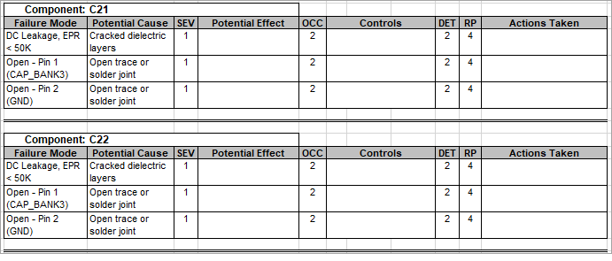
It's important to note that you may define as many rows inside of each template list as needed to achieve the desired output. In this case, a double-line and some high-lighted cells are output at the start of each Component to improve readability. Then, a basic header and border format is used to list each of the failure modes for a given component.
When generating spreadsheets that span multiple printed pages, the <PageHeader> and </PageHeader> tags can be used to designate one or more rows to be repeated at the top of each printed page. As with other template lists, individual template variables may be referenced, but no other template lists may be nested inside of the PageHeader list. Such repeating rows are typically used to display project and circuit card properties, and perhaps repeating column headers. For example, the 00-Backup-Template.xls template defines a basic page header to display the project and circuit card name on every printed page, as shown here:
In fact, that template shows how each of the template features can be used to export all DFMEA data to a spreadsheet file that can be easily parsed by another application. Sherlock users need only add template variables whenever they define a new DFMEA property to maintain a comprehensive template.
The same template used to export DFMEA data from Sherlock can be used to import DFMEA data from a spreadsheet into Sherlock. This allows Sherlock users to both import DFMEA data initially from existing spreadsheets and to export data from Sherlock, modify it using a spreadsheet application and then use that spreadsheet to update the Sherlock DFMEA Data Tree.
Any spreadsheet that was generated by Sherlock using a given template file can be easily imported by Sherlock using the same template file. Basically, the same template file defines not only how to generate the spreadsheet, but also how it can be parsed to import data. As long as the spreadsheet format remains consistent with the template, you may add, modify or delete DFMEA data in the spreadsheet and successfully update Sherlock using that spreadsheet. This allows users to seamlessly switch back-and-forth between Sherlock and their spreadsheet application for viewing and maintaining DFMEA data.
To see how the basic export-modify-import cycle works, select the C22 part entry in the DFMEA data tree (assigned to the Motor Controller - Right Side sub-circuit) and generate a spreadsheet using the 05-Part-Template.xls template file:
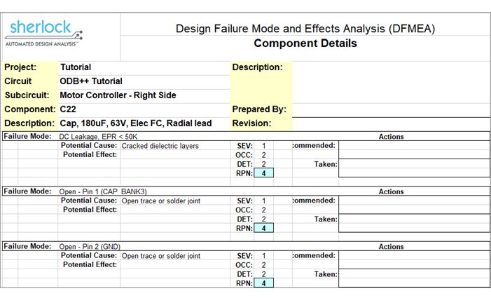
In this example, we see that there are no Potential Effect values indicated for any of the failure modes. We could use Sherlock to modify those values individually or we can update them in the spreadsheet file just generated and then update Sherlock using that spreadsheet, as we now demonstrate.
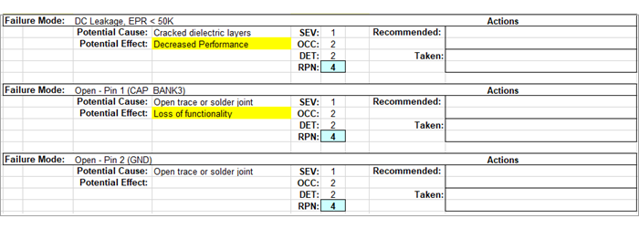
Modify the spreadsheet to define values for the first two failure modes, as highlighted here in yellow:
After saving the spreadsheet changes, right-click the top-level ODB++ Tutorial entry in the DFMEA Data Tree and select Import DFMEA Data from the context menu to display the Import DFMEA Data dialog.
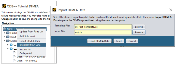
As a convenience, Sherlock automatically displays the last template file used, as well as the name of the last output file to be used as the input file. If different files are desired, simply press the Browse buttons to locate the proper files.
In this case, we are re-importing the file that we just generated, so the default values are correct. Press the Load DFMEA Data button to parse the input file and begin the import process.
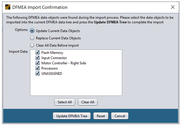
If the input file is parsed successfully, the DFMEA Import Confirmation dialog will be displayed. The confirmation dialog displays a tree showing all the DFMEA data entries found in the input file, as well as a list of processing options.
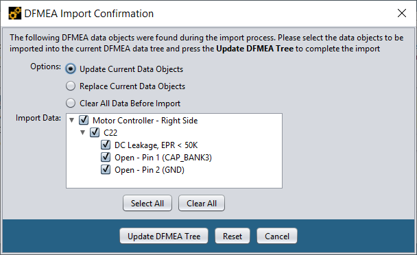
In this example, we want to update the current DFMEA data maintained by Sherlock using all the data found in the input file. As such, select Update Current Data Objects as the processing option and select all entries in the Import Data Tree. Finally, press the Update DFMEA Tree button to complete the import process. After the import process has completed, a quick review of the C22 failure modes will show that we now have Potential Effect values specified for the first two failure modes, just like they were specified in the spreadsheet.
The Replace Current Data Objects processing option is similar to the update option, except that it removes all existing properties and entries associated with a given entry before importing the data found in the spreadsheet. Similarly, the Clear All Data Before Import removes all DFMEA data from the Sherlock tree before importing data from the input file. These processing options exist to quickly replace all or part of the DFMEA tree with the data contained in the input file.
Note: Always use caution when selecting the Replace or Clear processing options. You will not be able to recover any data lost from Sherlock once you've pressed the Update DFMEA Tree button.
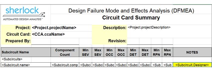
You can combine custom property definitions and the import process to quickly add data values to any DFMEA data tree. For example, in our previous examples, we added the Subcircuit / Designer property to the dfmeaProperties.csv file, but we haven't specified any values for that property, and we haven't referenced that template variable in any template. Let's remedy that situation with a simple template modification.
First, right-click the Main Board entry in the DFMEA data tree and select Export DFMEA Data from the context menu. Then, select the 01-CCA-Summary-Template.xls template file and generate a spreadsheet containing a summary list of all sub-circuits.
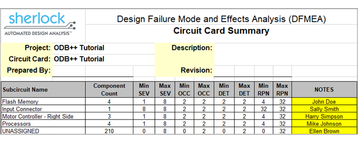
Use the Notes cell to enter the designer information for each sub-circuit, such as highlighted here:
After saving the data changes in the spreadsheet, we can now modify the template file to import those values using the customized template variable:
After saving the template change, we're ready to import the missing data by right-clicking the Main Board DFMEA tree entry, selecting Import DFMEA Data and using the modified template and spreadsheet files.
As before, we want to update the existing DFMEA data using all the data values imported from the spreadsheet. After the data has been imported, a quick review of the DFMEA Data Tree will show that all the designer data has been successfully added.
Note: When importing data, Sherlock automatically ignores data values associated with the min, max and count internal properties supported for sub-circuits and parts because those values are automatically generated by Sherlock. Similarly, all RPN values imported from a spreadsheet are also ignored.
Organizations that have existing DFMEA spreadsheets can import the data from those spreadsheets into Sherlock using the same import approach described above by creating a template file that represents the structure of the existing spreadsheet. For example, if the spreadsheet contains a fixed number of rows containing basic project and management information, those rows can simply be copied to the template file. If the spreadsheet then contains one or more rows for a given failure mode, a single copy of those rows can be copied to the template and placed inside of nested <Subcircuits>, <Components>, and <FailureModes> template lists. Finally, replace the values in that sample row by the appropriate subcircuit, part, or failure mode template variable. If additional properties are needed, simply add them to the dfmeaProperties.csv definition file to cause them to appear in the DFMEA data displays in Sherlock and to be imported from the input spreadsheet.
When modifying spreadsheet files, it is easy to add unnecessary rows or improperly modify cell values. In such cases, the resulting spreadsheet will probably not be consistent with the template used by Sherlock to process that file. In such cases, Sherlock will display an error dialog like the following:

In this case, Sherlock was not able to match the value found in cell (7,2) with the value expected by the template file (Subcircuit Name). This problem occurred because someone added an unexpected row to the spreadsheet file, as highlighted here in orange:
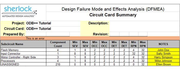
The problem can be corrected by either (a) removing the offending row from the spreadsheet file or (b) adding a similar row to the template file (if the orange row is really supposed to be there).
In addition to the DFMEA data management capabilities described above, Sherlock provides an analysis module that generates summary results based on the RPN values assigned in the DFMEA data. Although such results are not used to generate the same types of scores provided by other Sherlock analysis modules, they can be used to either get an overall view of the DFMEA data associate with a given circuit card to determine where best to spend additional effort.
The DFMEA results are generated by right-clicking the Analysis > DFMEA entry in the Sherlock Project Tree for a given circuit card and selecting the Edit Properties item from the context menu to display the properties dialog:
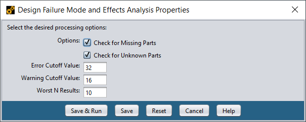
The properties dialog allows you to select various processing options, with the following options supported:
Table 6.11: Processing Options
| Processing Option | Description |
| Check for Missing Parts | Generates an error for any part contained in the Parts List that is not referenced by at least one subcircuit in the DFMEA data |
| Check for Unknown Parts | Generates an error for any part referenced in the DFMEA data that does not exist in the Parts List |
The dialog also allows you to specify the cutoff values to be used when color coding results. RPN values greater than or equal to the Error Cutoff Value are colored as errors (red), while values greater than or equal to the Warning Cutoff Value are colored as warnings (yellow). All other results will be colored green. After selecting the desired processing options and specifying the desired cutoff values, press the Save & Run button to save the properties and run the analysis task (or you can simply Save the properties to be used for a subsequent analysis run).
After the analysis task has completed successfully, double-click the Analysis > DFMEA entry in the Sherlock Project Tree to view the DFMEA results, including:
Summary Results
RPN Distribution Chart
DFMEA Ratings Table
Worst RPN table
Processing Issues
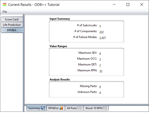
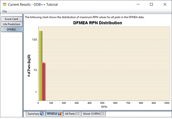
The Summary tab shows various counts and statistics gleaned from the DFMEA data. The maximum values shown are across all subcircuits, parts and failure modes associated with the current circuit card. The RPN Dist tab shows a graphical distribution of the maximum RPN values assigned to each part in the DFMEA data.
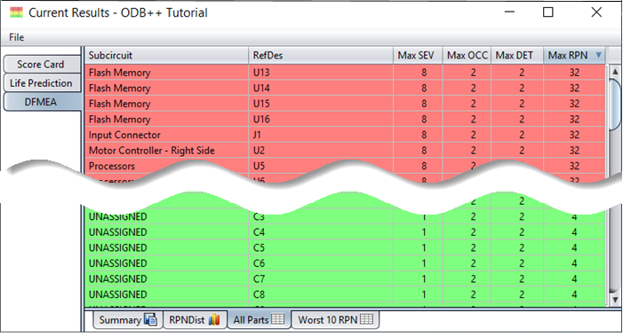
The All Parts tab shows a list of all parts defined in the DFMEA Tree and the maximum ratings assigned to the failure modes associated with those parts. (See table below.)
The rows in the table are color-coded based on the cutoff values defined in the analysis properties dialog. The table is initially sorted by decreasing RPN values, but you may single-click any column header to sort by that column. (Repeated clicks toggle between ascending and descending order.)
The Worst N RPN tab displays a list of the worst number of specified RPN values. This number is specified in the Worst N Results which can be changed in the DFMEA Properties. In this example, we have specified ten in the Worst N Results, and should therefore expect a table of ten worst RPN values.
Finally, an Issues tab lists may also appear. This tab lists any issues generated during the analysis process.
In addition to the tabular and graphical results described above, the DFMEA module also generates a collection of graphical layers that display color-coded parts based on the maximum RPN value assigned in the DFMEA data.
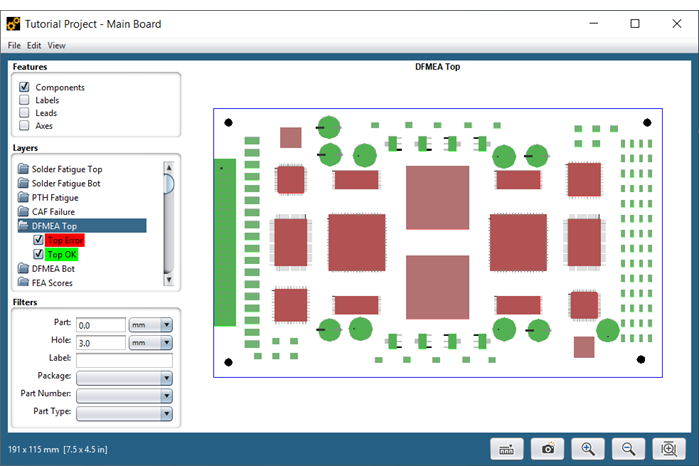
In this example, we can see each of the DFMEA parts color-coded the same as their corresponding rows in the tabular result. This location-based view of the results clearly shows the critical regions of the board that need to be examined further to improve their DFMEA ratings.
A circuit card Net List defines all electrical connections between component pins as a list of pin and network combinations. Pins that are electrically connected will be matched with the same network name. Sherlock uses the Net List when generating default Pin Open Failures and Pin Short Failures.
Importing Net List Data
Sherlock automatically imports Net List data when processing ODB++, IPC-2581, or Eagle CAD files, requiring no additional user input. For other projects, however, users must supply a CSV/XLS or a standard IPC-D-356 formatted file containing the Net List data. Once the file has been added to the Files list for a given circuit card, select the Net List (CSV/XLS) or Net List (IPC) depending on the imported file type, and Sherlock will load all the net list data found in the file.
Viewing Net List Data
For review purposes, the Net List data associated with a given circuit card can be viewed by double-clicking the Inputs >> Net List entry in the Project Tree. At that point, the Net List tab will be displayed in the Content Panel, showing the Net Name, Reference Designator and Pin Name for each network connection.
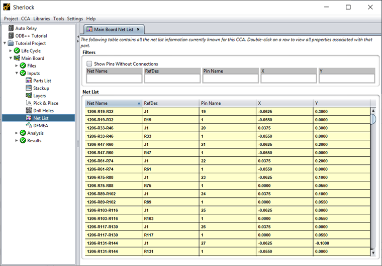
You may sort by any column and/or filter by rows containing specific substrings. You may also double-click any row to see the corresponding part properties. Finally, Net List data can be exported from the table using the standard Sherlock export capabilities.