


Nine blades and nine splitter blades are displayed.
Now that the geometry has been loaded in BladeEditor, you can modify it. Instructions for doing this are provided in the following sections:
In this section, you will make changes to the angle and thickness distributions of the main blade as follows:
Adjust the camberline at the hub by changing the leading edge Beta angle
Set the thickness distribution at the hub to a constant value from leading edge to trailing edge
Adjust the camberline at the shroud, and use a Bezier spline to control the Beta distribution
Note: These changes will also affect the splitter blade because the splitter blade currently inherits the angle and thickness distributions from the main blade. Later in this tutorial, you will change the thickness distribution of the splitter blade without affecting the main blade.
Start by adjusting the camberline at the hub:
In the Tree Outline view, select
Blade1>Blade1_Camberline1.The Angle and Thickness views for
Blade1_Camberline1are displayed.The Angle view displays one or two curves, one of which has control points along it. The curve with control points shows whatever is specified by the Angle Definition Type and X-Axis Definition Type properties of the blade.
In the Details View, set the Angle Definition Type to
Beta.Right-click anywhere in the Angle view and select
Convert to Bezier.In the Ansys BladeEditor dialog box that appears, set Number of Points to
5and click .Click the angle curve that has control points.
That angle curve becomes a Bezier spline controlled by 5 points.
In the Angle view, double-click the leftmost point on the graph to manually type in its coordinates.
Set the coordinates to
0, 40and press Enter.
Note: If you drag any of the points using the mouse, the curve will be adjusted accordingly. If any other changes are made, for example, by using the shortcut menu, you must then click the curve to update it.
Next, set the thickness at the hub to a constant value from leading edge to trailing edge, as follows:
Right-click anywhere in the Thickness view, and select Delete Point.
In the Thickness view select the point near the middle of the graph to delete it.
A straight line should now form, because there are two points remaining.
Double-click the leftmost point to manually set its coordinates.
Set the coordinates to
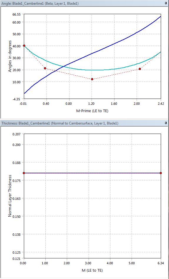
0, 0.18and press Enter.The straight line should now be completely horizontal, as in Figure 10.18: Angle and Thickness Views at Hub After Modifications below.
Click Generate
 .
.
Finally, adjust the camberline at the shroud, as follows:
In the Tree Outline view select
Blade1>Blade1_Camberline5.The Angle and Thickness views for
Blade1_Camberline5are displayed.Right-click anywhere in the Angle view, and select Convert to Bezier.
In the Ansys BladeEditor dialog box that appears, set the number of points to
6and click .Click the angle curve that has control points.
That angle curve becomes a Bezier spline controlled by 6 points.
Double-click the fourth point (counting from the left) to manually set its coordinates.
Set the coordinates to
0.5, 10and press Enter.Click Generate
.
You have changed the angle and thickness distributions of the main blade; these changes have been inherited by the splitter blade.
After the main blade has been designed, the splitter blade will already have the same angle and thickness distributions by default. In this section, you will modify the thickness distribution of the splitter blade alone without affecting the main blade.
In the Tree Outline view select
Splitter1>Splitter1_Camberline1.Set Thickness Definition to
User Specified.Right-click anywhere in the Thickness view, and select Convert to Bezier.
In the Ansys BladeEditor dialog box, set Number of Points to
4.Click the curve (not a point on the curve) in the Thickness view.
The curve is replaced by a similar curve with fewer control points.
Thicken the blade by increasing the Y-values of the control points to a maximum of approximately
0.25.Click Generate
.
You have changed the thickness distribution of the splitter blade without affecting the main blade.
Note: Setting Thickness Definition to From Reference Blade and then to User Specified has the effect of resetting the thickness distribution to that of
the main blade.