


The analysis modules that use FEA techniques generate similar results, which usually includes a Summary Panel, one or more tabular results, one or more graphical results layers and a 3D results file. We now discuss some of the common features for these results.
In addition to module-specific summary results, each FEA module displays a summary of Board Properties, PCB Properties and Analysis Process Times. Such information is most useful when reviewing results at a later time to determine which model was being used during the analysis. Shown below is an example of a Harmonic Vibe result:
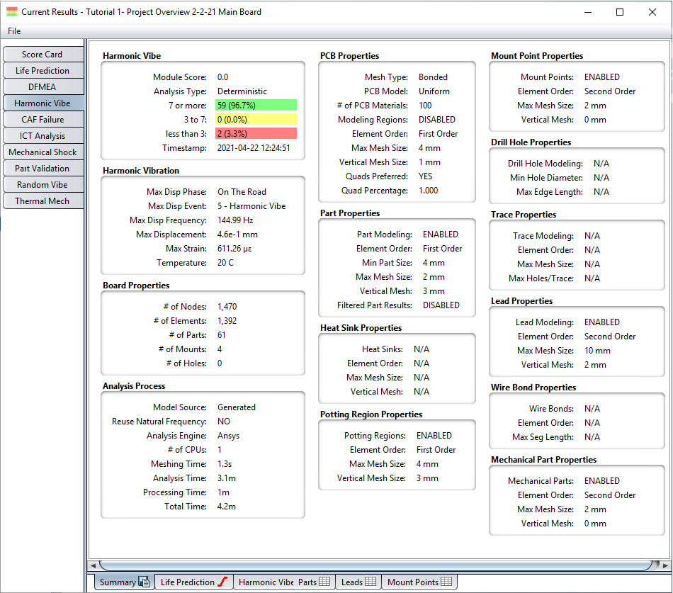
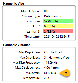
A closeup of the module-specific summary results is shown below. For Random Vibe, Harmonic Vibe, ICT, and Mechanical Shock, the overall Max Strain result (see A, below) is displayed. For Thermal Mech, max delta strain is displayed. Max strain the maximum PCB surface strain seen on either the top or bottom surface (applies to Ansys or Abaqus analysis only). For NX Nastran, the Max Strain represents the maximum nodal strain seen across the entire assembly.
The Board Properties section indicates the complexity of the FEA model used during the analysis. Processing time is generally related to the number of elements contained in the model. The number of parts, mount points, and holes are also provided for reference purposes. The number of nodes and elements here are for the PCB itself and does not include all other objects in the model. The numbers generated are specifically the number of nodes and elements generated for a single layer of the PCB. In this case, since the board is three layers, there are three times as many elements for the PCB as shown here.
The PCB Properties section indicates the settings used when the PCB model was created. In this case, a Bonded model was generated. The Quads Preferred option toggled to YES indicates that quad elements were desired in the mesh, as confirmed by the Quad Percentage value of 0.989.
The Part Properties section indicates the setting used when the part models were created. In this case, the Min Part Size to be included in the analysis is 0 mm, indicating that all parts were included for analysis. You can also see how the part mesh settings differ from the PCB mesh settings, making both mesh settings customizable.
The Analysis Process section indicates which FEA engine was used for the analysis, the number of CPUs used and some of the key processing times. In this case, a majority of the time was spent analyzing the model, as opposed to processing the FEA results and generating the reliability results. As mentioned earlier, Ansys is the default analysis engine. If you choose to use NX Nastran or Abaqus, that engine will be shown in the analysis process panel when you run the analysis.
If Part Modeling is enabled, you can filter the list to see only the parts that interest you. Tabular FEA Results are generated to show the maximum displacement and strain values experienced by each part during the simulation, as well as the score assigned to each part. For example, here's a tabular result for the Random Vibe module:
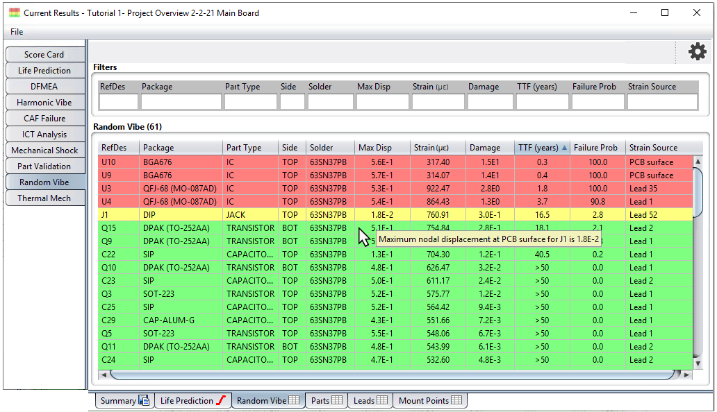
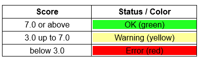
In this case, most parts have been colored RED, indicating that they were assigned a score below 3.0. Such color coding provides a quick and easy way to determine which parts need to be examined in detail. By default, the following coloring scheme is used for FEA results:
You can customize the score-color mapping by using the Settings >Score dialog to specify different cutoff values for each status color. The score-color settings will be used the next time that the analysis module is executed.
The Random Vibe, Harmonic Vibe, ICT, and Mechanical Shock results tables have the following additional features:
The results tables include tooltips for most cells. For other modules, tooltips appear on some secondary results tables such as leads, mount points, and wire bonds.
You can add or remove columns to customize the kind of results you want to see. Simply click the gear icon in the upper-right of the table to open the Column Settings dialog.
The Strain column in the main results table indicates the maximum PCB surface strain for components without lead modeling. For leaded components, it is the maximum elemental mean strain in the lead.
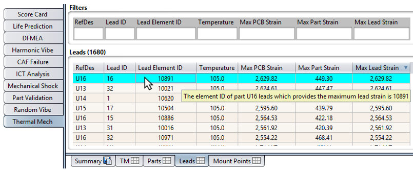
The secondary results tables may be configured to include a Lead Element ID column. In the example above, the element reporting the Max Lead Strain for part U16 is element 10891.
For tables that do not provide predictions, the Color Settings dialog (select Settings > Color from the main menu) allows you to set the table background color. Simply edit the colors for the Result Table Row and the Result Table Alt Row.
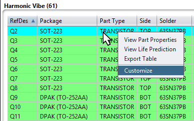
The main results table may be configured to include the Strain Source column which is used to show the source of the Strain value for a given component. This will either be the PCB surface or the lead number which provides the largest strain for the component. To add or remove the Strain Source (or any) column, right-click any cell on the table and select Customize. This will open the Column Settings dialog.
All FEA modules generate 2D graphical layers that show the scores assigned to each part and the displacement and strain values experienced by the PCB during the simulation.
Additionally, the 2D graphical results for Random Vibe, Harmonic Vibe, ICT, and Mechanical Shock have the following features:
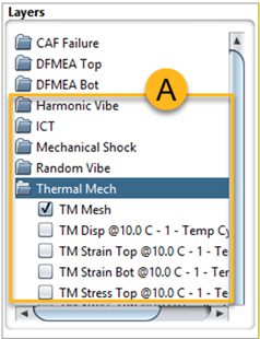
When you run an FEA analysis, Sherlock creates a folder in the Layer Viewer for that analysis. (See A, below and the highlighted analysis folders: Harmonic Vibe, ICT, and so on.) These folders include items from FEA Scores, FEA Results, and other layers.
FEA strain is reported in terms of microstrain. To change this setting, refer to the earlier section Analysis Properties.
FEA layer results contain both top and bottom layer strain results.
FEA layer results contain top and bottom layer surface Von-Mises Equivalent Stress results.
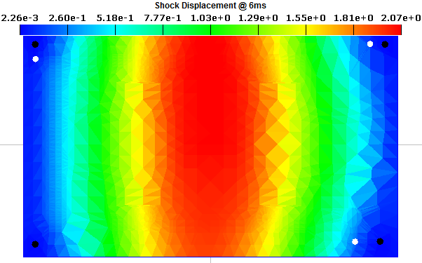
Sherlock's 2D displays are useful for quickly determining which regions of the PCB need improvement. For example, the following layer shows the score assigned to each part as the result of an ICT analysis. The score-color mapping is the same as that used for the ICT tabular results.
Displacement and strain results are displayed using a color spectrum to show the range of values across the entire PCB. The exact mapping of displacement values to the color range depends on the Displacement Color Settings defined in the Settings > FEA Analysis dialog, as shown below.
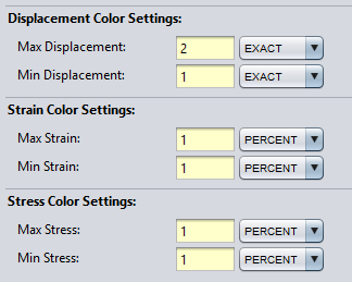
Specifically, all values above the Max Displacement Value will be colored RED, while all values below the Min Displacement Value will be colored BLUE. All values in between those values will be colored using the corresponding spectrum color. In this case, the min and max values are defined as percentages, indicating that color spectrum covers the middle 98% of the result values.
The Display Quality property found in the Settings > Meshing dialog can also be used to alter the display properties for 2D graphical result layers, supporting both Coarse and Fine display modes.
The smaller triangles with interpolated results not only smooth out the colored regions, but they provide better clarity. The fine layer clearly shows areas of high strain along the edge of each IC, which are not as apparent in the coarse rendering. All results are the same, just easier to see when using the fine setting.
Note: Coarse/Fine settings do not apply to the Random Vibe, Harmonic Vibe, ICT, Mechanical Shock, or Thermal Mech modules. The analysis results for these modules are based on elemental averaging and colored accordingly. Likewise, the Color Value option does not apply to Strain and Stress results.
In addition to the 2D graphical results layers, FEA modules also generate a 3D results file containing the complete 3D elemental model, as well as color mappings for each of the analysis results. For example, here's a 3D representation of the tutorial board:
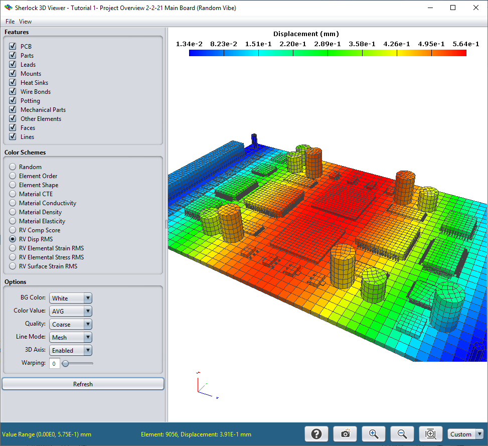
The 3D model and/or results can be viewed by right-clicking any FEA module entry in the Project Tree and selecting the View 3D Model or View 3D Results options in the context menu. See Viewing and Managing Analysis Results for more details.
If the Show FEA Logs option is enabled in the Settings > FEA Analysis dialog under Engine Properties, then a Log Panel will be displayed along with the other analysis results engine during the analysis process. Advanced users can review such log data to determine if everything was processed as expected and/or to trouble-shoot FEA processing issues.