Ansys Icepak 's solar load model enables you to include the effects of direct solar illumination as well as diffuse solar radiation. Given the model geometry and pertinent solar information such as terrestrial location, date, and time, the model performs a ray tracing shading test for all boundary surfaces. This approach includes a two-band (visible and infrared) spectral model for solar illumination. The transparent material model computes the absorptivity and transmissivity as functions of incident angle.
User Inputs for the Solar Load Model
Ansys Icepak provides a solar calculator that can be used to compute solar beam direction and irradiation. Alternatively you can specify a value for the Direct solar irradiation, Diffuse solar irradiation flux and the sun direction vector. To use the solar load model, follow the procedure outlined below.
In the Advanced tab of the Basic parameters panel, turn on the Solar loading option and click Options to open the Solar Load Model parameters panel.
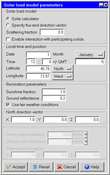
In the Solar load model parameters panel, the default option is Solar calculator. You will need to specify the following parameters:
Under Solar load model, specify a value for Scattering fraction. The scattering fraction specifies the amount of direct solar radiation that is reflected from opaque objects in your model. The reflected radiation is evenly distributed among all objects that participate in solar loading. The value should be between 0 and 1. If you select Enable interaction with participating solids, Icepak models the solar irradiation as discrete ordinate fluxes at the cabinet boundaries. This allows semi-transparent walls and participating solids to absorb, refract and scatter the incident solar irradiation. This option is only available if the Discrete Ordinates radiation model is selected.
Under Local time and position. specify a value for the Date and select the month from the Month menu.
Specify the local time at the desired location in the two fields to the right of Time. The time is based on a 24-hour clock, therefore acceptable values range from 0 h 0 min (12:00 a.m.) to 23 h 59.99 min (11:59:99 p.m.). Values entered in the first text-entry field (hour) must be integral, but values entered in the second text-entry field (minute) can be integral or fractional. For example, if the local time was 12:01:30 a.m., you would enter 0 for the hour and 1.5 for the minute. If the local time was 4:17 p.m., you would enter 16 for the hour and 17 for the minute.
Specify the local time zone of the desired location using the offset value to the right of the +/- GMT entry fields. If the time you enter is a local time, specify the current time zone by providing the offset in the +/- GMT entry. If the time you enter is already in GMT, then +/- GMT should be set to 0 (zero).
Note: For example, the figure above shows +/- GMT of -5, which is Eastern Standard Time (EST).
Specify the Local Latitude of the desired location. Values can range from
-90° (the South Pole) to90° (the North Pole), with 0° defined as the equator. Select the hemisphere (N or S) from the menu to the right of the Local Longitude entry field.Specify the Local Longitude of the desired location. The longitude is approximated if you specify the local time zone, but you can enter a more precise value if you know it. Any value you enter here will take precedence over the time zone. Values may range from
0° to180°. Select the hemisphere (W or E) from the menu to the right of the Local Longitude entry field.Under Illumination parameters, specify the following parameters:
Specify the Sunshine fraction, which is a factor between 0 and 1 used to account for the effects of clouds that may reduce the direct solar irradiation. Clear sky is modeled by setting the value equal to 1 and complete cloud cover is modeled by setting the value equal to 0. Partial cloud cover is modeled by setting the value to be between 0 and 1. The default value is 1.0.
Specify the Ground reflectance, which is a parameter that is used in determining the contributions of reflected solar radiation from ground surfaces. Reflected solar radiation from ground surfaces is a function of the direct normal irradiation, the time of the year, the tilt angle of the surface, and the ground reflectance. If is treated as part of the total diffuse solar irradiation. Ground reflectance values can vary depending on the ground surface (that is, concrete, grass, rock, gravel, asphalt). The default value is 0.2.
If you select Use fair weather conditions, the calculated solar load is attenuated to simulate fair-weather atmospheric conditions. If the option is unchecked, the solar irradiaton calculation assume clear weather conditions.
Specify the Northward direction vector. To specify this vector, enter the appropriate values in the X, Y, and Z fields under Northward direction. Note that the default northward direction in Ansys Icepak is the x direction.
Specify the surface material to be used for each object or surface. This surface defines the roughness, emissivity, solar behavior, and the solar absorption and transmission parameters of the surface. For each material, select one of the following options next to Solar behavior:
Opaque indicates that the surface will not allow solar radiation to pass through it.
Transparent indicates that the surface will allow a portion of the solar radiation to pass through it.
By default, the surface material is specified as Opaque. This means that the material specified on the object or surface is defined under Default surface in the Default tab of the Basic parameters panel (see Default Fluid, Solid, and Surface Materials). To change the material for an object or surface, select a material from the material drop-down list. See Material Properties for details on material properties.
In the Solar Load Model parameters panel, you can select the Specify flux and direction vector option. You will need to specify the following parameters under Solar flux and direction vector:
Specify a value for Direct solar irradiation. This parameter is the amount of energy per unit area due to direct solar irradiation. This value may depend on the time of the year and the clearness of the sky.
Specify a value for Diffuse solar irradiation. This parameter is the amount of energy per unit area due to diffuse solar irradiation. This value may depend on the time of year, the clearness of the sky, and also on ground reflectivity.
Enter the Solar direction vector. To specify this vector, enter the appropriate values in the X, Y, and Z fields.
Note: The solar load model does not work on any side of objects that overlap non-conformal assembly boundary.
Modifying Solar Participation
When solar loading is enabled, all objects are set to paricipate by default. You can modify solar participation settings from the Basic parameters panel or from the context menu in the project tree or graphics display window.
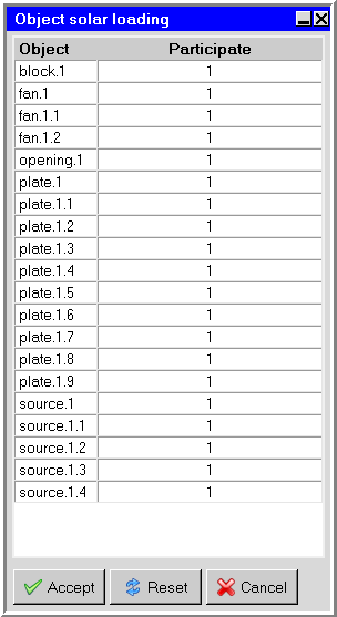
From the Basic parameters Advanced tab under Solar loading, click Edit. In the Object solar loading panel, enter 0 to disable or 1 to enable solar loading participation for a given object.
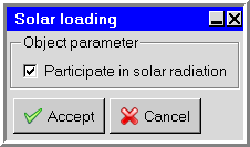
From the context menu (in the project tree or graphics display window), select Set > Solar particpation. In the Solar loading panel, select Particpate in solar radiation to include the object in the solar loading calculation.