


You can reposition an object in Ansys Icepak in much the same way as you reposition a cabinet. See Repositioning the Cabinet for details on repositioning a cabinet. Note that you can also reposition an object (and the cabinet) using a local coordinate system as described Local Coordinate Systems.
You should note the following differences between repositioning an object and repositioning a cabinet:
To modify the plane of the currently selected object (if relevant), click the Plane text entry field in the object Edit panel (for example, Figure 9.12: Example of an Object Edit Window) to open a list of available planes (yz, xz, and xy), and select a new plane from the list. The plane of the currently selected object can also be specified in the Object panel (for example, Figure 9.14: Example of an Object Panel (Geometry Tab)) using the Plane drop-down list, where you can choose Y-Z, X-Z, or X-Y.
There are several options related to moving an object using the mouse that are available for objects but not for the cabinet. These options are displayed in the Interaction section of the Preferences panel (Figure 9.10: The Interaction Section of the Preferences Panel) and are listed below:
X, Y, Z enable you to select which combination of the three axes along which the object can be translated. For example, if you are positioning an opening on a wall, you would want to limit the motion of the opening to only two coordinate directions in order to move the opening across the surface of the wall.
Restrict movement to cabinet enables you to restrict the motion of the object to within the cabinet boundaries. If In cabinet is not selected, Ansys Icepak will enable the object to project beyond the cabinet boundaries. This option is on by default for all objects.
Objects can't penetrate each other instructs Ansys Icepak not to allow any penetration of the object by another object. This option is on by default for all objects.
Move object also moves group enables you to move entire groups using the Shift key and the middle mouse button.
Move object snaps to other objects enables you to snap objects to other objects using the Shift key and the middle mouse button.
Snap Tolerance specifies the distance, in pixels, within which a moved object will be snapped to another object. When this value has been set, and the model is oriented in one of the X, Y, or Z views, a dragged object will automatically snap into alignment with a second object of similar shape when it comes within the specified number of pixels of a vertex, line, or plane of the second object.
New object size factor specifies the default size of a newly-created object in terms of the size of the cabinet. For example, in a 1 m
 1 m
1 m  1 m cabinet, a value of 0.2 specifies that new objects will
have side lengths of 0.2 m.
1 m cabinet, a value of 0.2 specifies that new objects will
have side lengths of 0.2 m. Note: This value does not apply to package objects.
If you click the
 button after selecting an object, Ansys Icepak will
open a Move object panel and not the Move all objects in model panel that is used for the cabinet.
You can also open the Move object panel by right-clicking
on an object in the list under the Model node
and selecting Move in the drop-down menu.
button after selecting an object, Ansys Icepak will
open a Move object panel and not the Move all objects in model panel that is used for the cabinet.
You can also open the Move object panel by right-clicking
on an object in the list under the Model node
and selecting Move in the drop-down menu. You can rotate the object about any coordinate axis. Select X, Y, or Z next to Axis, and then select 90, 180, 270, -90, -180, or -270 degrees of rotation. The object can also be rotated about a Point or its Centroid. Enter coordinates when rotating about a Point.
If multiple geometric transformations are selected, Ansys Icepak applies them in the order that they appear in the panel. For example, if both the Rotate and Translate options are selected, the new object is rotated first and then translated. Note that not all combinations of transformations are commutative; that is, the result may be order-dependent, particularly if reflection is used.
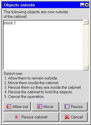
If you specify a transformation that moves an object outside the cabinet, Ansys Icepak opens the Objects outside panel (Figure 9.18: The Objects outside Panel), which contains the following options:
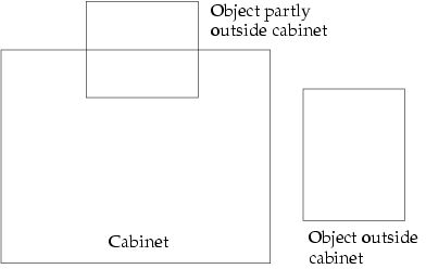
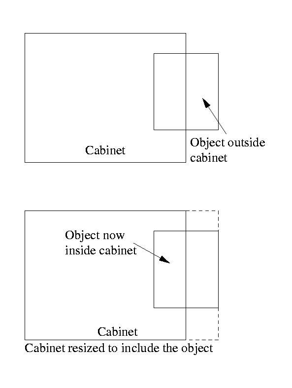
Allow out instructs Ansys Icepak to let the object remain outside the cabinet boundary. The object can be either completely outside the cabinet or partly outside the cabinet, as shown in Figure 9.19: Object Outside Cabinet Boundary. This option can be used if the cabinet you have created is too small and you want to resize the cabinet at a later time.
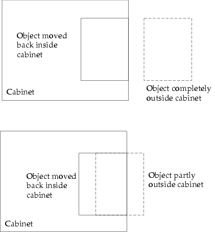
Move instructs Ansys Icepak to move the object back inside the cabinet. The object is moved back inside the cabinet as shown in Figure 9.20: Moving the Object Back Inside the Cabinet, where the dashed line shows the position of the object before the move, and the solid line shows the position of the object after the move.
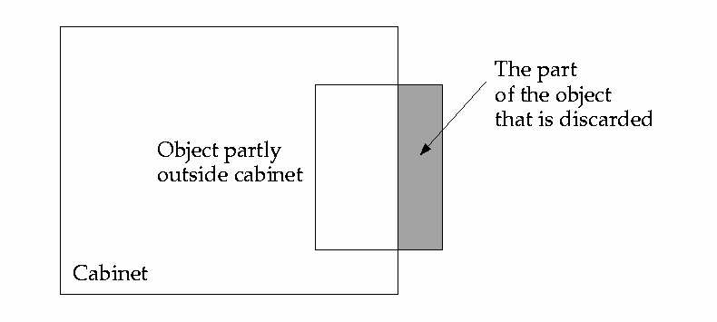
Resize instructs Ansys Icepak to resize the object so that it is inside the cabinet. Ansys Icepak will change the object so that only the part of the object that is inside the cabinet after the transformation remains in the model, as shown in Figure 9.21: Resizing an Object that is Outside the Cabinet. The part that is outside will be discarded.
Resize cabinet instructs Ansys Icepak to resize the cabinet so that the object is inside the cabinet, as shown in Figure 9.22: Resizing the Cabinet to Include Outside Object.
Cancel instructs Ansys Icepak to cancel the move operation that caused the object to either exceed the cabinet dimension or be placed outside the cabinet.
Local Coordinate Systems
The global coordinate system has an origin of (0, 0, 0) in Ansys Icepak. You can create local coordinate systems that can be used in your model. The origins of the local coordinate systems are specified with an offset from the origin of the global coordinate system.
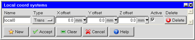
The Local coord systems panel can be used to view and manage all local coordinate systems in your Ansys Icepak model. To open the Local coord systems panel (Figure 9.23: The Local coord systems Panel), double-click the Local coords item under the Problem setup node in the Model manager window.
![]() Problem setup
Problem setup 
 Local coords
The Local coord systems panel can be used to create new local coordinate systems, edit existing local coordinate systems, and delete or deactivate local coordinate systems. These operations are described below.
Each Object panel (for example, Figure 9.14: Example of an Object Panel (Geometry Tab)), and also the Cabinet panel (Figure 9.6: The Cabinet Panel (Geometry Tab)), contains a Local coord system drop-down list. To select a local coordinate system for an object (or for the cabinet), open the Local coord system list and select a local coordinate system from the list. If the Local coord system field is empty, the global coordinate system will be used for the object (or cabinet).
The Local coord system list can also be used to create a new local coordinate system, edit an existing local coordinate system, and view the definition of the selected local coordinate system. These operations are described in the following section.